5
Regulatory Information
The HCPL-7560 has been approved by the following organizations:
IEC/EN/DIN EN 60747-5-2
Approved under:
IEC 60747-5-2:1997 + A1:2002
EN 60747-5-2:2001 + A1:2002
DIN EN 60747-5-2 (VDE 0884 Teil 2):2003-01.
UL
Approval under UL 1577, component recognition program up to V
ISO
= 3750 V
RMS
. File E55361.
CSA
Approval under CSA Component Acceptance Notice #5, File CA 88324.
IEC/EN/DIN EN 60747-5-2 Insulation Characteristics
[1]
Notes:
1. Insulation characteristics are guaranteed only within the safety maximum ratings, which must be ensured by protective circuits within the
application. Surface Mount Classications is Class A in accordance with CECC00802.
2. Refer to the optocoupler section of the Isolation and Control Components Designer’s Catalog, under Product Safety Regulations section, (IEC/
EN/DIN EN 60747-5-2) for a detailed description of Method a and Method b partial discharge test proles.
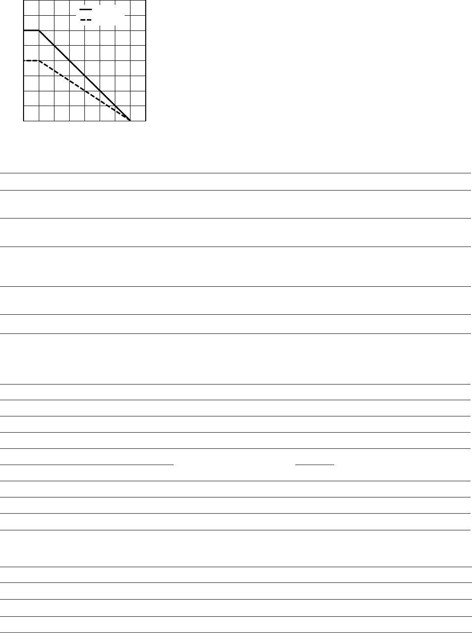
3. Refer to the following gure for dependence of P
S
and I
S
on ambient temperature.
Description Symbol HCPL-7560 Unit
Installation classication per DIN VDE 0110/1.89, Table 1
for rated mains voltage ≤ 300 Vrms
for rated mains voltage ≤ 450 Vrms
for rated mains voltage ≤ 600 Vrms
I - IV
I - III
I - II
Climatic Classication 40/85/21
Pollution Degree (DIN VDE 0110/1.89) 2
Maximum Working Insulation Voltage V
IORM
891 V
peak
Input to Output Test Voltage, Method b
[2]
V
IORM
x 1.875=V
PR
, 100% Production Test with t
m
=1 sec,
Partial discharge < 5 pC
V
PR
1670 V
peak
Input to Output Test Voltage, Method a
[2]
V
IORM
x 1.5=V
PR
, Type and Sample Test, t
m
=60 sec,
Partial discharge < 5 pC
V
PR
1336 V
peak
Highest Allowable Overvoltage
(Transient Overvoltage t
ini
= 10 sec)
V
IOTM
6000 V
peak
Safety-limiting values - maximum values allowed in the event of a failure,
also see Figure 13.
Case Temperature
Input Current
[3]
Output Power
[3]
T
S
I
S, INPUT
P
S, OUTPUT
175
400
600
°C
mA
mW
Insulation Resistance at T
S
, V
IO
= 500 V R
S
>10
9
W