LTC2954
10
2954fb
Figure 1. Simplified Power On/Off Sequence for LTC2954-1. μP Asserts KILL After an Interrupt
Figure 2. KILL Remaining Low Aborts Power-On Sequence for LTC2954-1
APPLICATIONS INFORMATION
t
1
t
2
t
DB, ON
XXX DON'T CARE
t
3
t
4
t
5
t
6
t
8
t
9
t
7
PB
ONT
PDT
EN
KILL
INT
PB & KILL IGNORED
2954 F01
t
KILL, ON BLANK
t
DB, OFF
t
PD, MIN
t
ONT
t < t
PDT
PB IGNORED
μP DRIVES
KILL LOW
t
ABORT
t
DB,ON
+ t
ONT
PB
KILL
POWER-ON
TIMING
EN
512ms
INTERNAL
TIMER
POWER
TURNED OFF
2954 F02
μP FAILED TO SET
KILL HIGH
LTC2954
11
2954fb
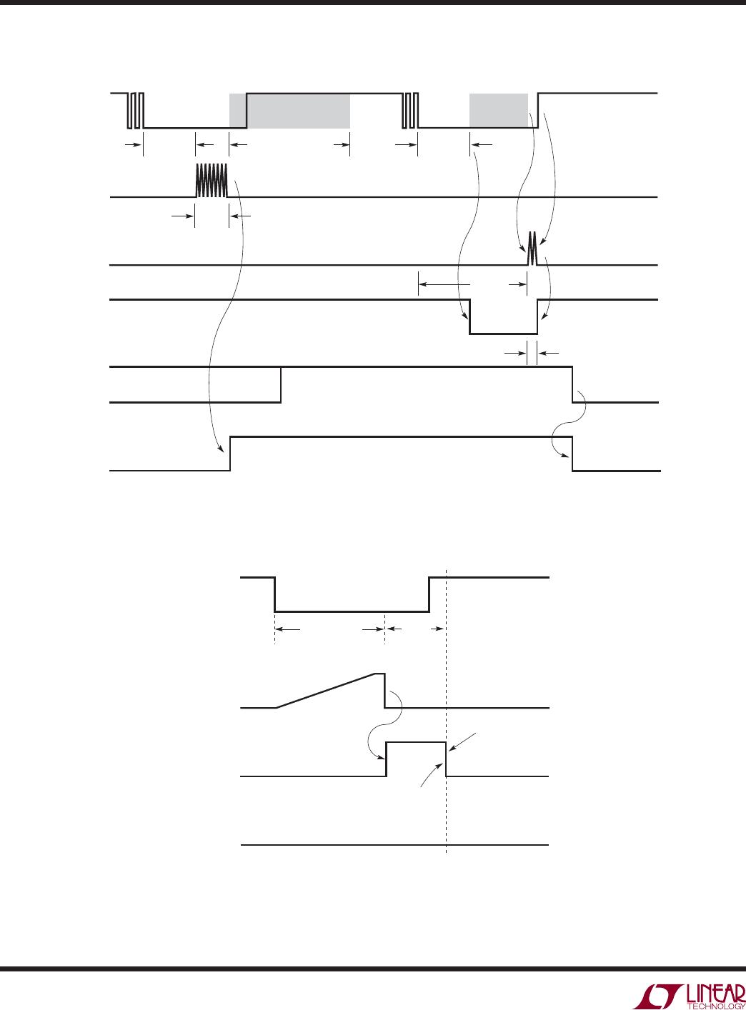
Aborted Power-On Sequence
The power-on sequence is aborted when the KILL remains
low at the end of the 512ms blanking time. Figure 2 is a
simplified version of an aborted power-on sequence. At
time t
ABORT
, since KILL is still low, EN pulls low (thus
turning off the DC/DC converter).
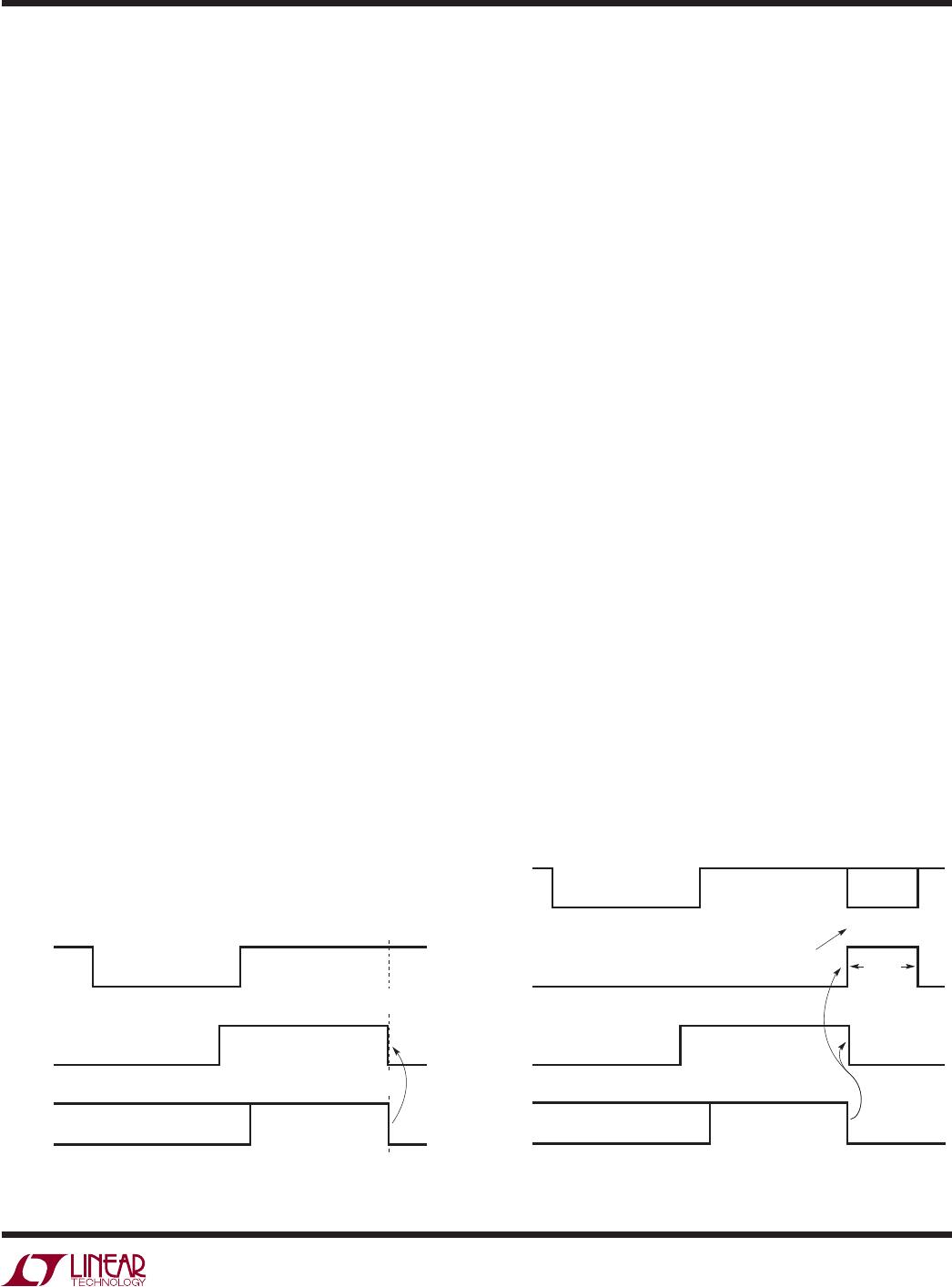
μP Turns Off Power During Normal Operation
Once the system has powered on and is operating nor-
mally, the μP can turn off power by setting KILL low, as
shown in (Figure 3). At time t
KILL
, KILL is set low by the
μP. This immediately pulls EN low, thus turning off the
DC/DC converter.
DC/DC Turn Off Blanking
When the DC/DC converter is turned off, it can take a sig-
nificant amount of time for its output to decay to ground. It
is desirable to wait until the output of the DC/DC converter
is near ground before allowing the user (via PB) to restart
the converter. This condition guarantees that the μP has
always powered down completely before it is restarted.
Figure 4 shows the μP turning power off. After a low on
KILL releases enable, the internal 256ms timer ignores the
PB pin. This is shown as t
EN/EN, LOCKOUT
in (Figure 4).
Figure 3. μP Turns Off Power (LTC2954-1) Figure 4. DC/DC Turn-Off Blanking (LTC2954-1)
low 512ms after it went high. Note that the LTC2954 does
not sample KILL and PB until after the 512ms internal timer
has expired. The reason PB is ignored is to ensure that
the system is not forced off while powering on. Once the
512ms timer expires (t
4
), the release of the PB pin is then
debounced with an internal 32ms timer. The system has
now properly powered on and the LTC2954 monitors PB
and KILL for a turn-off command while consuming only
6μA of supply current.
A high to low transition on PB (t
5
) starts the power-off
sequence debounce timer. In order to assert the interrupt
output (INT), PB must stay low continuously (PB high
resets debounce timer) for 32ms (t
6
–t
5
). At the comple-
tion of the power-down debounce timer (t
6
), an internal
interrupt timer keeps the interrupt output low for at least
32ms, even if PB is released between t
6
and t
7
. If PB is
low at the end of this 32ms internal timer (t
7
), the external
adjustable power-down timer is started. The capacitor
placed at the PDT pin will determine the time period of
this timer. If the pushbutton is released prior to 16 cycles
of the PDT pin, the interrupt output will go high (t
8
). Note
that the enable output is not directly changed by this
interrupt pulse. The function of the interrupt signal is to
initiate a software shutdown. At t
9
, the μP has performed
its power-down functions and asserted the KILL input
low. This releases the enable output, which in turn shuts
down system power. Note that if the pushbutton is held
long enough to count 16 cycles at the PDT pin, the enable
pin would be released immediately after the 16th cycle.
The system is now in its reset state where the LTC2954 is
in low power mode (6μA) and PB is monitored for a high
to low transition.
APPLICATIONS INFORMATION
t
KILL
PB
EN
DC/DC
TURNS OFF
2954 F03
KILL
XXX DON’T CARE
μP SETS
KILL LOW
PB
PB IGNORED
EN
KILL
PB BLANKING
(INTERNAL
SIGNAL)
XXX DON’T CARE
256ms
POWER ON
2954 F04
DC/DC
TURNS OFF
μP SETS
KILL LOW
t
EN/EN, LOCKOUT
LTC2954
12
2954fb
LTC2954-1, LTC2954-2 Versions
The LTC2954-1 (high true EN) and LTC2954-2 (low true
EN) differ only by the polarity of the high voltage (33V ABS
MAX), enable pin. The LTC2954-1 EN pin is a low leakage
high true open drain output designed to drive the shutdown
pin of DC/DC converters. The LTC2954-2 is a low leakage,
low true open drain enable output designed to drive the
gate of an external PFET. The LTC2954-2 provides a user
manual power path control.
High Voltage Pins
The V
IN
, PB and EN/EN pins can operate at voltages up to
26.4V. PB can, additionally, operate below ground (–6V)
without latching up the device. PB has an ESD HBM rating
of ±10kV. If the pushbutton switch connected to PB exhib-
its high leakage current, then an external pull-up resistor
to V
IN
is recommended. Furthermore, if the pushbutton
switch is physically located far from the LTC2954 PB pin,
parasitic capacitances may couple onto the high imped-
ance PB input. Additionally, parasitic series inductance
may cause unpredictable ringing at the PB pin. Placing
a 5.1k resistor from the PB pin to the pushbutton switch
would mitigate parasitic inductance problems. Placing a
0.1μF capacitor on the PB pin would lessen the impact of
parasitic capacitive coupling.
Figure 5. Input Voltage Monitoring with KILL Input Figure 6. No μP Application
Voltage Monitoring with KILL Input
The KILL pin can be used as a voltage monitor. Figure 5
shows an application where the KILL pin has a dual func-
tion. It is driven by a low leakage open drain output of the
μP. It is also connected to a resistive divider that monitors
battery voltage (V
IN
). When the battery voltage falls be-
low the set value, the voltage at the KILL pin falls below
0.6V and the EN pin is quickly pulled low. Note that the
resistor values should be as large as possible, but small
APPLICATIONS INFORMATION
PB
V
IN
V
OUT
SHDN**
V
IN
= 9V
EN
INT
KILL
INT
KILL
(OPEN DRAIN)
LTC2954-1
GND
ONT PDT
LT1767-3.3
μP
R1
10k
3.3V
2954 F05
C4
0.1μF
R3
806k
1%
R2
100k
1%
* OPTIONAL
** SHDN INTERNALLY PULLED
UP BY THE LT1767-3.3
V
IN
C
ONT
*
0.033μF
C
PDT
*
F
V
IN
= 9V
3.3V
R1
100k
C3*
0.01μF
2954 F06
+
C4
0.1μF
PB
EN
INT
KILL
LTC2954-1
GND ONT PDT
V
IN
C
ONT
*
0.033μF
C
PDT
*
F
* OPTIONAL
** SHDN INTERNALLY
PULLED UP BY
THE LT1767-3.3
V
IN
V
OUT
SHDN**
LT1767-3.3
TYPICAL APPLICATIONS
enough to keep leakage currents from tripping the 0.6V
KILL comparator.
The DC/DC converter shown has an internal pull-up cur-
rent on its SHDN pin. A pull-up resistor on EN is thus not
needed.
Operation Without μP
Figure 6 shows how to connect the KILL pin when there
is no circuitry available to drive it. The minimum pulse

LTC2954CTS8-1#TRMPBF

Mfr. #:
Manufacturer:
Analog Devices Inc.
Description:
Supervisory Circuits Push Button On/Off Controller with U Interrupt for Menu Driven Applications
Lifecycle:
New from this manufacturer.
Delivery:
DHL FedEx Ups TNT EMS
Payment:
T/T Paypal Visa MoneyGram Western Union