7
FN8184.1
September 14, 2005
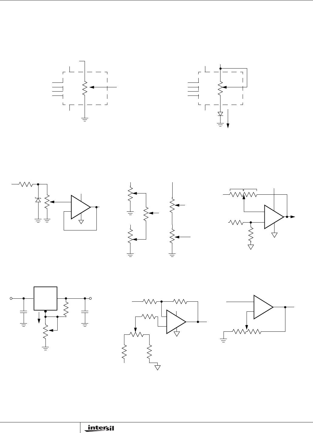
INSTRUCTIONS AND PROGRAMMING
The INC
, U/D and CS inputs control the movement of
the wiper along the resistor array. With CS
set LOW
the device is selected and enabled to respond to the
U/D
and INC inputs. HIGH to LOW transitions on INC
will increment or decrement (depending on the state of
the U/D
input) a seven bit counter. The output of this
counter is decoded to select one of one hundred wiper
positions along the resistive array.
The value of the counter is stored in nonvolatile mem-
ory whenever CS
transitions HIGH while the INC input
is also HIGH.
The system may select the X9318, move the wiper
and deselect the device without having to store the lat-
est wiper position in nonvolatile memory. After the
wiper movement is performed as described above and
once the new position is reached, the system must
keep INC
LOW while taking CS HIGH. The new wiper
position will be maintained until changed by the sys-
tem or until a powerup/down cycle recalled the previ-
ously stored data.
This procedure allows the system to always power-up
to a preset value stored in nonvolatile memory; then
during system operation minor adjustments could be
made. The adjustments might be based on user pref-
erence, system parameter changes due to tempera-
ture drift, etc.
The state of U/D
may be changed while CS remains
LOW. This allows the host system to enable the
device and then move the wiper up and down until the
proper trim is attained.
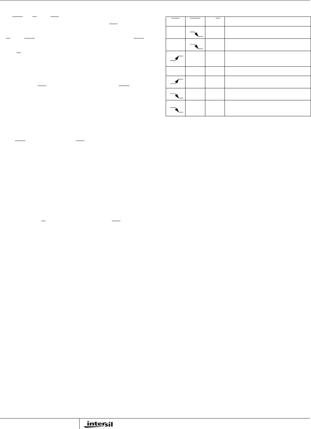
MODE SELECTION
CS
INC U/D Mode
L H Wiper up
L L Wiper down
HX
Store wiper position to
nonvolatile memory
H X X Standby
L X No store, return to standby
L H Wiper Up (not recommended)
LL
Wiper Down
(not recommended)
X9318
8
FN8184.1
September 14, 2005
APPLICATIONS INFORMATION
Electronic digitally controlled (XDCP) potentiometers provide three powerful application advantages; (1) the variability
and reliability of a solid-state potentiometer, (2) the flexibility of computer-based digital controls, and (3) the retentivity
of nonvolatile memory used for the storage of multiple potentiometer settings or data.
Basic Configurations of Electronic Potentiometers
Basic Circuits
V
REF
R
W
V
REF
I
Three terminal potentiometer;
variable voltage divider
Two terminal variable resistor;
variable current
R
H
R
L
Cascading TechniquesBuffered Reference Voltage
+
+5V
R
1
+V
V
REF
V
OUT
LMC7101
R
W
R
W
+V
+V +V
X
(a) (b)
V
OUT
= V
W
/R
W
Single Supply Inverting Amplifier
Voltage Regulator
R
1
R
2
I
adj
V
O
(REG) = 1.25V (1+R
2
/R
1
)+I
adj
R
2
V
O
(REG)V
IN
317
Offset Voltage Adjustment
+
V
S
V
O
R
2
R
1
100k
10k10k
10k
+12V
LMC7101
Comparator with Hysteresis
V
UL
= {R
1
/(R
1
+R
2
)} V
O
(max)
V
LL
= {R
1
/(R
1
+R
2
)} V
O
(min)
+
R
1
V
O
LMC7101
+
V
S
V
O
R
2
R
1
}
}
LT311A
(for additional circuits see AN115)
+12V
R
2
+8V
100K
100K
+8V
V
S
V
O
= (R2/R1)V
S
R
W
X9318
9
FN8184.1
September 14, 2005
PACKAGING INFORMATION
0.150 (3.80)
0.158 (4.00)
0.228 (5.80)
0.244 (6.20)
0.014 (0.35)
0.019 (0.49)
Pin 1
Pin 1 Index
0.010 (0.25)
0.020 (0.50)
0.050 (1.27)
0.188 (4.78)
0.197 (5.00)
0.004 (0.19)
0.010 (0.25)
0.053 (1.35)
0.069 (1.75)
(4X) 7°
0.016 (0.410)
0.037 (0.937)
0.0075 (0.19)
0.010 (0.25)
0° - 8°
X 45°
8-Lead Plastic Small Outline Package, Type S (8-lead SOIC)
NOTE: ALL DIMENSIONS IN INCHES (IN PARENTHESES IN MILLIMETERS)
0.250"
0.050"Typical
0.050"
Typical
0.030"
Typical
8 PlacesFOOTPRINT
X9318

X9318WS8IZ

Mfr. #:
Manufacturer:
Renesas / Intersil
Description:
Digital Potentiometer ICs 100-TAP 10KOHMUP/DWN INTERFA NON-VOLATILE
Lifecycle:
New from this manufacturer.
Delivery:
DHL FedEx Ups TNT EMS
Payment:
T/T Paypal Visa MoneyGram Western Union