General Description
The MAX9597 single SCART interface routes audio and
video signals between a set-top box decoder chip and
an external SCART connector under I
2
C control.
Operating from a 3.3V supply and a 12V supply, the
MAX9597 consumes 53mW during quiescent operation
and 254mW during average operation when driving
typical signals into typical loads.
The MAX9597 audio section contains left and right audio
paths with an independent operational amplifier at the
inputs. The DirectDrive
®
output amplifiers create a
2V
RMS
full-scale audio signal biased around ground,
eliminating the need for bulky output capacitors and
reducing click-and-pop noise. The zero-cross detection
circuitry also further reduces clicks and pops by
enabling audio sources to switch only during a zero-
crossing.
The MAX9597 video section contains 4 channels of
video filter amplifiers. The standard-definition video sig-
nals from the set-top box decoder chip are lowpass fil-
tered to remove out-of-bandwidth artifacts. The
MAX9597 also supports slow-switching and fast-switch-
ing signals.
The MAX9597 is available in a compact 28-pin thin
QFN package and is specified over the 0°C to +70°C
commercial temperature range.
Features
53mW Quiescent Power Consumption
5µW Shutdown Consumption
Audio Operational Amplifiers to Create Input
Filters
Clickless/Popless, DirectDrive Audio
Video Reconstruction Filter with 10MHz Passband
and 43dB Attenuation at 27MHz
3.3V and 12V Supply Voltages
MAX9597
Low-Power Audio/Video Interface
for Single SCART Connectors
________________________________________________________________
Maxim Integrated Products
1
19-4159; Rev 1; 10/08
For pricing, delivery, and ordering information, please contact Maxim Direct at 1-888-629-4642,
or visit Maxim’s website at www.maxim-ic.com.
EVALUATION KIT
AVAILABLE
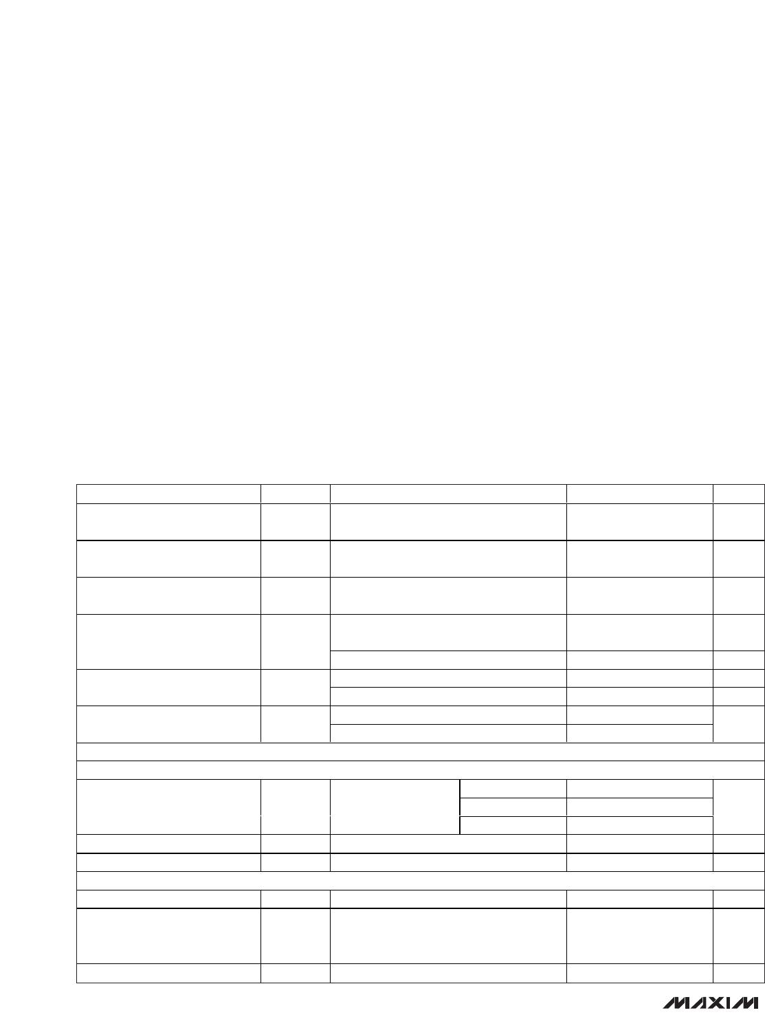
Ordering Information
+
Denotes a lead-free/RoHS-compliant package.
*
EP = Exposed pad.
PART TEMP RANGE PIN-PACKAGE
MAX9597CTI+ 0°C to +70°C 28 TQFN-EP*
I
2
C INTERFACE
AND REGISTERS
MAX9597
VIDEO FILTERS
AUDIO
WITH DirectDrive
OUTPUTS
SLOW SWITCHING
FAST SWITCHING
CHARGE PUMP
V
12
V
AUD
V
ID
12V 3.3V3.3V
EP
GND
µC
VIDEO
ENCODER
STEREO
AUDIO
DAC
RGB, Y/C, CVBS
SINGLE OR
DIFFERENTIAL
STEREO AUDIO
STB CHIP
I
2
C
RGB, Y/C, CVBS
L/R AUDIO
FAST AND SLOW SWITCHING
TV
SCART
System Block Diagram
Applications
Set-Top Boxes
AV Receivers
TVs
DVD Players
DirectDrive is a registered trademark of Maxim Integrated
Products, Inc.
MAX9597
Low-Power Audio/Video Interface
for Single SCART Connectors
2 _______________________________________________________________________________________
ELECTRICAL CHARACTERISTICS
(V
VID
= V
AUD
= 3.3V, V
12
= 12V, GND = EP = 0, no load, T
A
= 0°C to +70°C, unless otherwise noted. Typical values are at
T
A
= +25°C.) (Note 1)
Stresses beyond those listed under “Absolute Maximum Ratings” may cause permanent damage to the device. These are stress ratings only, and functional
operation of the device at these or any other conditions beyond those indicated in the operational sections of the specifications is not implied. Exposure to
absolute maximum rating conditions for extended periods may affect device reliability.
PARAMETER SYMBOL CONDITIONS MIN TYP MAX UNITS
Video Supply Voltage Range V
VID
Inferred from video PSRR test at 3.0V and
3.6V
3.0 3.3 3.6 V
Audio Supply Voltage Range V
AUD
Inferred from audio PSRR tests at 3.0V and
3.6V
3.0 3.3 3.6 V
Slow-Switching Supply Voltage
Range
V
12
Inferred from slow-switching levels 11.4 12 12.6 V
Normal operation, all video output
amplifiers are enabled
13 20 mA
V
VID
Quiescent Supply Current I
VID_Q
Shutdown 1 10 µA
Normal operation 3 4.1 mA
V
AUD
Quiescent Supply Current I
AUD_Q
Shutdown 0.01 10 µA
Normal operation 1.5 100
V
12
Quiescent Supply Current I
12_Q
Shutdown 0.1 10
µA
VIDEO CHARACTERISTICS
DC-COUPLED INPUT
V
VID
= 3V 1.15
V
VID
= 3.135V 1.2
Input Voltage Range V
IN
R
L
= 75 to GND or
150 to V
VID
/2,
inferred from gain test
V
VID
= 3.3V 1.3
V
P-P
Input Current I
IN
V
IN
= GND 2 3 µA
Input Resistance R
IN
300 k
AC-COUPLED INPUT
Sync-Tip Clamp Level V
CLP
Sync-tip clamp -5 0 6.1 mV
Sync Crush
Sync-tip clamp; percentage reduction in
sync pulse (0.3V
P-P
); guaranteed by input
clamping current measurement
2%
Input Clamping Current Sync-tip clamp 2 3 µA
ABSOLUTE MAXIMUM RATINGS
(All voltages referenced to GND, unless otherwise noted.)
V
VID
..........................................................................-0.3V to +4V
V
12
to EP ................................................................-0.3V to +14V
V
AUD
to EP ...............................................................-0.3V to +4V
EP to GND .............................................................-0.1V to +0.1V
All Video Inputs .......................................................-0.3V to +4V
All Audio Inputs to EP .............................(V
EP
- 1)V to (V
EP
+ 1)V
SDA, SCL, DEV_ADDR ............................................-0.3V to +4V
TV_SS_OUT .................................................-0.3V to (V
12
+ 0.3V)
Current
All Video/Audio Inputs ..................................................±20mA
C1P, C1N, CPVSS ........................................................±50mA
Output Short-Circuit Current Duration
All Video Outputs, TV_FS_OUT to V
VID
, GND........Continuous
Audio Outputs to V
AUD
, EP ....................................Continuous
TV_SS_OUT to V
12
, EP...........................................Continuous
Continuous Power Dissipation (T
A
= +70°C)
28-Pin Thin QFN
(derate 21.3mW/°C above +70°C)...........................1702mW
Operating Temperature Range ..............................0°C to +70°C
Junction Temperature .....................................................+150°C
Storage Temperature Range .............................-65°C to +150°C
Lead Temperature (soldering, 10s) .................................+300°C
MAX9597
Low-Power Audio/Video Interface
for Single SCART Connectors
_______________________________________________________________________________________ 3
PARAMETER SYMBOL CONDITIONS MIN TYP MAX UNITS
Max Input Source Resistance 300
Bias Voltage V
BIAS
Bias circuit 0.57 0.6 0.63 V
Input Resistance Bias circuit 10 k
DC CHARACTERISTICS
V
VID
= 3V,
V
IN
= V
CLP
to
(V
CLP
+ 1.15V)
2
V
VID
= 3.135V,
V
IN
= V
CLP
to
(V
CLP
+ 1.2V)
1.93 2 2.05
V
VID
= 3V,
V
IN
= (V
BIAS
- 0.575V)
to (V
BIAS
+ 0.575V)
2
DC Voltage Gain A
V
R
L
= 75
to GND
or
R
L
= 150
to V
VID
/2
V
VID
= 3.135V
V
IN
= (V
BIAS
- 0.6V)
to (V
BIAS
+ 0.6V)
1.93 2 2.05
V/V
DC Gain Mismatch Guaranteed by DC voltage gain -2 +2 %
Sync-tip clamp 0.2 0.30 0.4
Output Level
Bias circuit 1.38 1.5 1.62
V
Sync-tip clamp, measured at
output, V
VID
= 3V, V
IN
= V
CLP
to (V
CLP
+ 1.15V), R
L
= 75
to GND or R
L
= 150 to
V
VID
/2
2.3
Measured at output, V
VID
=
3.135V, V
IN
= V
CLP
to (V
CLP
+ 1.2V), R
L
= 75 to GND or
R
L
= 150 to V
VID
/2
2.316 2.4 2.46
Bias circuit, measured at
output, V
VID
= 3V, V
IN
=
(V
BIAS
- 0.575V) to (V
BIAS
+
0.575V), R
L
= 75 to GND or
R
L
= 150 to V
VID
/2
2.3
Output Voltage Swing
Guaranteed
by DC
voltage gain
Measured at output, V
VID
=
3.135V, V
IN
= (V
BIAS
- 0.6V)
to (V
BIAS
+ 0.6V), R
L
= 75
to GND or R
L
= 150 to
V
VID
/2
2.316 2.4 2.46
V
P-P
Output Short-Circuit Current 100 mA
Output Leakage Current Output disabled 0.02 10 µA
Power-Supply Rejection Ratio 3.0V V
VID
3.6V 50 75 dB
ELECTRICAL CHARACTERISTICS (continued)
(V
VID
= V
AUD
= 3.3V, V
12
= 12V, GND = EP = 0, no load, T
A
= 0°C to +70°C, unless otherwise noted. Typical values are at
T
A
= +25°C.) (Note 1)

MAX9597CTI+T

Mfr. #:
Manufacturer:
Maxim Integrated
Description:
Multimedia ICs Video ICs A/V Switch for Dual SCART Connecto
Lifecycle:
New from this manufacturer.
Delivery:
DHL FedEx Ups TNT EMS
Payment:
T/T Paypal Visa MoneyGram Western Union

Products related to this Datasheet