MAX9597
Low-Power Audio/Video Interface
for Single SCART Connectors
______________________________________________________________________________________ 25
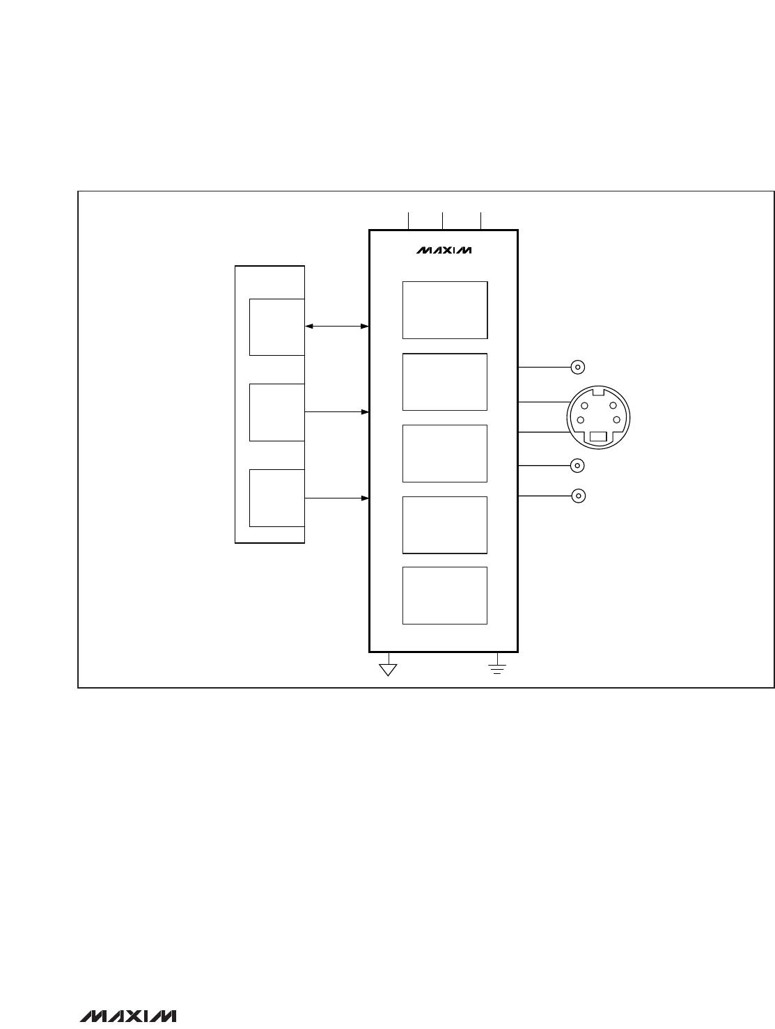
The MAX9597 provides separate ground connections
for video and audio supplies. For best performance,
use separate ground planes for each of the ground
returns and connect all ground planes together at a sin-
gle point. Refer to the MAX9597 Evaluation Kit for a
proven circuit board layout example.
If the MAX9597 is mounted using flow soldering or
wave soldering, the ground via(s) for the exposed pad
should have a finished hole size of at least 14mil to
ensure adequate wicking of soldering onto the exposed
pad. If the MAX9597 is mounted using the solder mask
technique, the via requirement does not apply. In either
case, a good connection between the exposed pad
and ground is required to minimize noise from coupling
onto the outputs.
4
3
2
1
I
2
C INTERFACE
AND REGISTERS
MAX9597
VIDEO FILTERS
AUDIO
WITH DirectDrive
OUTPUTS
SLOW SWITCHING
FAST SWITCHING
CHARGE PUMP
V
12
V
AUD
V
ID
3.3V3.3V
EP
GND
µC
VIDEO
ENCODER
STEREO
AUDIO
DAC
CVBS, Y/C
SINGLE OR
DIFFERENTIAL
STEREO AUDIO
STB CHIP
CVBS
Y
C
LEFT AUDIO
RIGHT AUDIO
I
2
C
N.C.
Figure 18. Set-Top Box with CVBS Output, S-Video Output, and Stereo Audio Outputs
MAX9597
Low-Power Audio/Video Interface
for Single SCART Connectors
26 ______________________________________________________________________________________
REGISTER
ADDRESS
(HEXADECIMAL)
BIT 7 BIT 6 BIT 5 BIT 4 BIT 3 BIT 2 BIT 1 BIT 0
0x00 Not used ZCD Not used
TV audio
mute
0x01 Not used
0x02 Not used
0x03 Not used
0x04 Not used
0x05 Not used
0x06 Not used
0x07 Not used
Not
used
Not used Set TV fast switching Not used Set TV slow switching
0x08 Not used
Not
used
Not used Not used
ENC_R/C_IN
clamp
Not used Not used
Not
used
0x09 Not used
0x0A Not used
0x0B Not used
0x0C Not used
0x0D Not used
Not
used
TV_R/C_OUT TV_G_OUT TV_B_OUT TV_CVBS_OUT TV_FS_OUT
Not
used
0x10
Operating
mode
Not
used
Not used Not used Not used Not used Not used
Not
used
Table 7. Data Format for Write Mode
Register Tables
MAX9597
Low-Power Audio/Video Interface
for Single SCART Connectors
______________________________________________________________________________________ 27
BIT
DESCRIPTION
76543210
COMMENTS
——————— 0Off
TV audio mute
——————— 1On (power-on default)
0 ——————Off
Zero-crossing detector
1 ——————On (power-on default)
Table 8. Register 00h: Audio Control
BIT
DESCRIPTION
76543210
COMMENTS
—————— 0 0
Low (< 2V) internal source (power-on
default)
—————— 0 1
Medium (4.5V to 7V) external SCART
source with 16:9 aspect ratio
—————— 1 0High impedance
Set TV slow switching
—————— 1 1
High ( > 9.5V) external SCART source
with 4:3 aspect ratio
0 0 GND (power-on default)
0 1 Not used
1 0 Same level as VCR_FB_IN
Set TV fast switching
——— 1 1 ——V
VID
Table 9. Register 07h: TV Video Output Control
BIT
DESCRIPTION
76543210
COMMENTS
———— 0 ———
DC restore clamp active at input
(power-on default)
ENC_R/C_IN clamp/bias
———— 1 ———Chrominance bias applied at input
Table 10. Register 08h: VCR Video Input Control

MAX9597CTI+T

Mfr. #:
Manufacturer:
Maxim Integrated
Description:
Multimedia ICs Video ICs A/V Switch for Dual SCART Connecto
Lifecycle:
New from this manufacturer.
Delivery:
DHL FedEx Ups TNT EMS
Payment:
T/T Paypal Visa MoneyGram Western Union

Products related to this Datasheet