AD8182ARZ-RL

AD8180/AD8182
–7–
REV. B
for R
L
> 10 k. For heavier loads, the dc gain is approximately
that of the voltage divider formed by the output impedance of
the mux (typically 27 ) and R
L
.
High speed disable clamp circuits at the bases of Q5–Q8 (not
shown) allow the buffers to turn off quickly and cleanly without
dissipating much power once off. Moreover, these clamps shunt
displacement currents flowing through the junction capacitances
of Q1–Q4 away from the bases of Q5–Q8 and to ac ground
through low impedances. The two-pole high pass frequency
response of the T switch formed by these clamps is a significant
improvement over the one-pole high pass response of a simple
series CMOS switch. As a result, board and package parasitics,
especially stray capacitance between inputs and outputs may
limit the achievable crosstalk and off isolation.
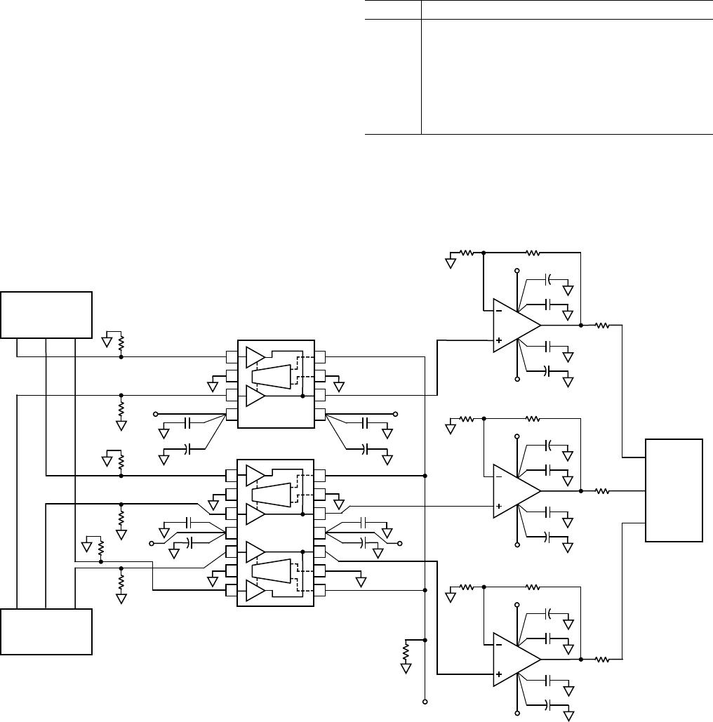
LAYOUT CONSIDERATIONS:
Realizing the high speed performance attainable with the
AD8180 and AD8182 requires careful attention to board layout
and component selection. Proper RF design techniques and low
parasitic component selection are mandatory.
Wire wrap boards, prototype boards, and sockets are not recom-
mended because of their high parasitic inductance and capaci-
tance. Instead, surface-mount components should be soldered
directly to a printed circuit board (PCB). The PCB should have
a ground plane covering all unused portions of the component
side of the board to provide a low impedance ground path. The
ground plane should be removed from the area near input and
output pins to reduce stray capacitance.
Chip capacitors should be used for supply bypassing. One end
of the capacitor should be connected to the ground plane and
the other within 1/4 inch of each power pin. An additional large
(4.7 µF–10 µF) tantalum capacitor should be connected in
parallel with each of the smaller capacitors for low impedance
supply bypassing over a broad range of frequencies.
Signal traces should be as short as possible. Stripline or micros-
trip techniques should be used for long signal traces (longer
than about 1 inch). These should be designed with a character-
istic impedance of 50 or 75 and be properly terminated at
the end using surface mount components.
Careful layout is imperative to minimize crosstalk. Guards
(ground or supply traces) must be run between all signal traces
to limit direct capacitive coupling. Input and output signal lines
should fan out away from the mux as much as possible. If mul-
tiple signal layers are available, a buried stripline structure hav-
ing ground plane above, below, and between signal traces will
have the best crosstalk performance.
Return currents flowing through termination resistors can also
increase crosstalk if these currents flow in sections of the finite-
impedance ground circuit that is shared between more than one
input or output. Minimizing the inductance and resistance of the
ground plane can reduce this effect, but further care should be
taken in positioning the terminations. Terminating cables directly
at the connectors will minimize the return current flowing on the
board, but the signal trace between the connector and the mux will
look like an open stub and will degrade the frequency response.
Moving the termination resistors close to the input pins will im-
prove the frequency response, but the terminations from neigh-
boring inputs should not have a common ground return.
THEORY OF OPERATION
The AD8180 and AD8182 video multiplexers are designed for
fast-switching (10 ns) and wide bandwidth (> 750 MHz). This
performance is attained with low power dissipation (3.8 mA per
active channel) through the use of proprietary circuit techniques
and a dielectrically-isolated complementary bipolar process.
These devices have a fast disable function that allows the out-
puts of several muxes to be wired in parallel to form a larger mux
with little degradation in switching time. The low disabled output
capacitance (1.7 pF) of these muxes helps to preserve the system
bandwidth in larger matrices. Unlike earlier CMOS switches,
the switched open-loop buffer architecture of the AD8180 and
AD8182 provides a unidirectional signal path with minimal switch-
ing glitches and constant, low input capacitance. Since the input
impedance of these muxes is nearly independent of the load imped-
ance and the state of the mux, the frequency response of the ON
channels in a large switch matrix is not affected by fanout.
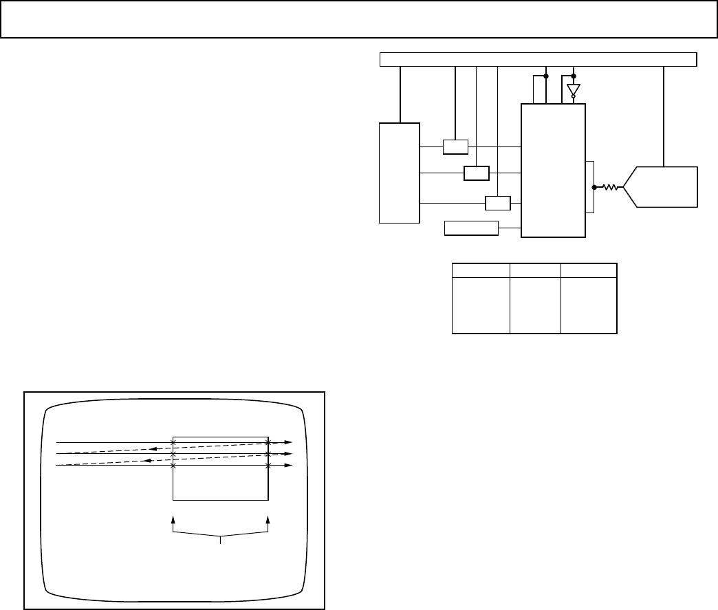
Figure 22 shows a block diagram and simplified schematic of the
AD8180, which contains two switched buffers (S0 and S1) that
share a common output. The decoder logic translates TTL-
compatible logic inputs (SELECT and ENABLE) to internal,
differential ECL levels for fast, low-glitch switching. The SELECT
input determines which of the two buffers is enabled, unless the
ENABLE input is HIGH, in which case both buffers are disabled
and the output is switched to a high impedance state.
Q5
Q7
Q3
Q1
S0
I1
I3
Q6
Q8
Q4
Q2
S1
I2
I4
DECODER
AD8180
1
2
3
4
IN0
GND
IN1
+V
S
8
7
6
5
–V
S
OUT
ENABLE
SELECT
Figure 22. Block Diagram and Simplified Schematic of the
AD8180 Multiplexer
Each open-loop buffer is implemented as a complementary
emitter follower that provides high input impedance, symmetric
slew rate and load drive, and high output-to-input isolation due to
its β
2
current gain. The selected buffer is biased ON by fast
switched current sources that allow the buffer to turn on quickly.
Dedicated flatness circuits, combined with the open-loop architec-
ture of the AD8180 and AD8182, keep peaking low (typically
< 1 dB) when driving high capacitive loads, without the need for
external series resistors at the input or output. If better flatness
response is desired, an input series resistance (R
S
) may be used
(refer to Figure 20), although this will increase crosstalk. The dc
gain of the AD8180 and AD8182 is almost independent of load
AD8180/AD8182
–8–
REV. B
APPLICATIONS
Multiplexing two RGB Video Sources
A common video application requires two RGB sources to be
multiplexed together before the selected signal is applied to a
monitor. Typically one source would be the PC’s normal output,
the second source might be a specialized source such as MPEG
video. Figure 23 shows how such a circuit could be realized
using the AD8180 and AD8182 and three current feedback op
amps. The video inputs to the multiplexers are terminated with
75 resistors. This has the effect of halving the signal amplitude
of the applied signals.
Because all three multiplexers are permanently active, the
ENABLE pins are tied permanently low. The three SELECT
pins are tied together and this signal is used to select the source.
In order to drive a 75 back terminated load (R
L
= 150 ), the
multiplexer outputs are buffered using the AD8001 current feed-
back op amp. A gain of two compensates for the signal halving by
the AD8001 output back termination resistor so that the system
has an overall gain of unity.
If lower speed and crosstalk can be tolerated, either of the triple
op amps, AD8013 or AD8073, can replace the three AD8001 op
amps in the above circuit. Because both devices have bandwidths
in the 100 MHz to 140 MHz range at a gain of +2, these ampli-
fiers will dominate the frequency response of the circuit.
With no signal present, the total quiescent current of the cir-
cuit in Figure 23 is 25.6 mA (3.8 mA + 6.8 mA + 3 × 5 mA), or
about 8.5 mA per channel. If either the AD8013 or AD8073
are used, the quiescent current will decrease to about 6.5 mA
per channel.
To reduce power consumption further, three AD8011 single
op amps can be used. With a quiescent current of 1 mA, this
will reduce the per channel quiescent current to about 4.5 mA.
Table II. Amplifier Options for RGB Multiplexer
Op Amp Comments
AD8001 Highest Bandwidth, 440 MHz (G = +2), I
SY
= 5 mA
AD8011 Lower Power Consumption, Bandwidth (G = +2) =
210 MHz, I
SY
= 1 mA
AD8013 Triple Op Amp, Bandwidth (G = +2) = 140 MHz,
I
SY
= 3.4 mA
AD8073 Lower Power Triple Op Amp, Bandwidth (G = +2) =
100 MHz, I
SY
= 3.5 mA
8
7
6
5
ENABLE
ENABLE A
–V
S
ENABLE B
–V
S
+V
S
0.1mF
10mF
0.1mF
10mF
0.1mF
+V
S
+
75V
75V
75V
75V
75V
75V
RGB
COMPUTER
GRAPHICS
RGB
+
+V
S
0.1mF
10mF
75V
681V
–V
S
+
10mF
0.1mF
+
+V
S
0.1mF
10mF
75V
681V
681V
–V
S
+
10mF
0.1mF
+
+V
S
0.1mF
10mF
75V
681V
–V
S
+
10mF
0.1mF
SELECT
MONITOR
1
2
3
4
AD8180
+1
+1
1
2
3
4
14
13
12
11
AD8182
5
6
7
10
9
8
DECODER
+1
+1
DECODER
+1
+1
+ +
MPEG
R
TERM
AD8001
681V
AD8001
681V
AD8001
R
G
B
0.1mF
10mF
+
10mF
DECODER
Figure 23. Multiplexing Two Component Video Sources
AD8180/AD8182
–9–
REV. B
Picture-in-Picture or Pixel Switching
Many high end display systems require simultaneous display of
two video pictures (from two different sources) on one screen.
Video conferencing is one such example. In this case the remote
site might be displayed as the main picture with a picture of the
local site “inset” for monitoring purposes. The circuit in Fig-
ure 23 could also be used to implement this “picture-in-picture”
application.
Implementing a picture-in-picture algorithm is difficult for
several reasons. Both sources are being displayed simultaneously
(i.e., during the same frame), both sources are in real time, and
both must be synchronized. Figure 24 shows the raster scan-
ning that takes place in all monitors. During every horizontal
scan that includes part of the inset, the source must be switched
twice (i.e., from main to inset and from inset to main). To avoid
screen artifacts, it is critical that switching is clean and fast. The
AD8180 and AD8182, in the above application, switch and
settle to 0.1% accuracy in 14 ns. We quadratically add this
value to the 10 ns settling time of the AD8001, and get an over-
all settling time of 17.2 ns. This yields a sharp, artifact-free
border between the inset and the main video.
INSET VIDEO
MULTIPLEXER MUST SWITCH
CLEANLY ON EACH CROSSING
MAIN VIDEO
Figure 24. “Picture-in-Picture,” Pixel Switching
Color Document Scanner
Figure 25 shows a block diagram of a Color Document Scan-
ner. Charge Coupled Devices (CCDs) find widespread use in
scanner applications. A monochrome CCD delivers a serial
stream of voltage levels, each level being proportional to the
light shining on that cell. In the case of the color image scanner
shown, there are three output streams, representing red, green
and blue. Interlaced with the stream of voltage levels is a voltage
representing the reset level (or black level) of each cell. A Corre-
lated Double Sampler (CDS) subtracts these two voltages from
each other in order to eliminate the relatively large offsets which
are common with CCDs.
CONTROL AND TIMING
AD876 8/10-BIT
20MSPS
A/D
AD8182
OUT A
OUT B
CDS
CDS
CDS
REFERENCE
R
G
B
C
C
D
IN0 A
IN1 A
IN1 B
IN0 B
100V
4:1 MUX TRUTH TABLE
SEL A, SEL B
ENA, ENB
OUTA, OUTB
0
0
1
1
0
1
0
1
IN0A
IN0B
IN1A
IN1B
EN A
EN B
SEL A
SEL B
Figure 25. Color Document Scanner
The next step in the data acquisition process involves digitizing
the three signal streams. Assuming that the analog to digital
converter chosen has a fast enough sample rate, multiplexing
the three streams into a single ADC is generally more eco-
nomic than using one ADC per channel. In the example
shown, we use the two 2-to-1 multiplexers in the AD8182 to
create a 4-to-1 multiplexer. The enable control pins on the
multiplexers allow the outputs to be wired directly together.
Because of its high bandwidth, the AD8182 is capable of driv-
ing the switched capacitor input stage of the AD876 without
additional buffering. In addition to having the required the
bandwidth, it is necessary to consider the settling time of the
multiplexer. In this case, the ADC has a sample rate of 20 MHz
which corresponds to a sampling period of 50 ns. Typically,
one phase of the sampling clock is used for conversion (i.e., all
levels are held steady) and the other phase is used for switch-
ing and settling to the next channel. Assuming a 50% duty cycle,
the signal chain must settle within 25 ns. With a settling time to
0.1% of 14 ns, the multiplexer easily satisfies this criterion.
In the example shown, the fourth (spare) channel of the
AD8182 is used to measure a reference voltage. This voltage
would probably be measured less frequently than the R, G and
B signals. Multiplexing a reference voltage offers the advantage
that any temperature drift effects caused by the multiplexer
will equally impact the reference voltage and the to-be-
measured signals. If the fourth channel is unused, it is good
design practice to tie this input to ground.

AD8182ARZ-RL

Mfr. #:
Manufacturer:
Analog Devices Inc.
Description:
Multiplexer Switch ICs Dual 2:1 Buffered 750MHz 3.8mA 10ns
Lifecycle:
New from this manufacturer.
Delivery:
DHL FedEx Ups TNT EMS
Payment:
T/T Paypal Visa MoneyGram Western Union