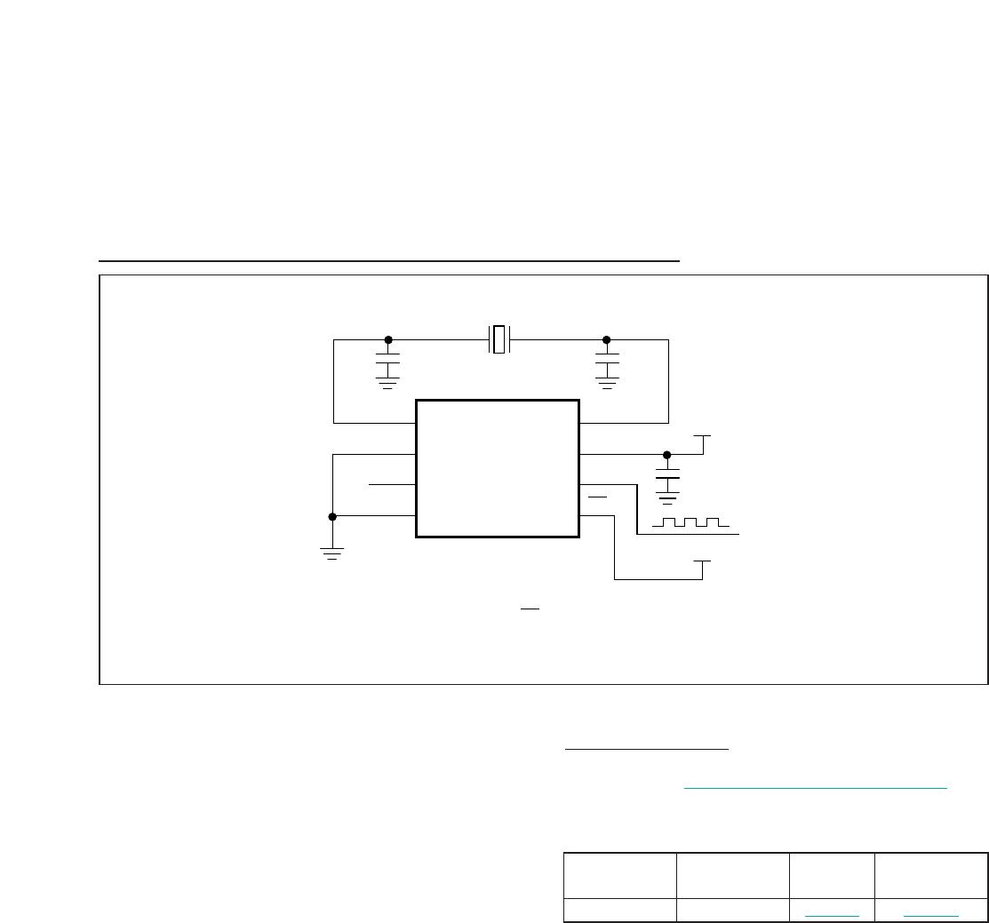
Spread-Spectrum Crystal Multiplier
DS1080L
Maxim Integrated cannot assume responsibility for use of any circuitry other than circuitry entirely embodied in a Maxim Integrated product. No circuit patent
licenses are implied. Maxim Integrated reserves the right to change the circuitry and specifications without notice at any time. The parametric values (min and
max limits) shown in the Electrical Characteristics table are guaranteed. Other parametric values quoted in this data sheet are provided for guidance.
8
Maxim Integrated 160 Rio Robles, San Jose, CA 95134 USA 1-408-601-1000
© 2013 Maxim Integrated Products, Inc. Maxim Integrated and the Maxim Integrated logo are trademarks of Maxim Integrated Products, Inc.
REVIS ION
NUMBER
REVIS ION
DATE
DESCRIPTION
PAGES
CHANGED
0 11/05 Initial release —
1 3/06
Changed V
IHMIN
from 0.7V x V
CC
to 0.08V x V
CC
and V
ILMAX
from 0.3 x V
CC
to 0.2V x V
CC
in the Recommended Operating Conditions t able
2
2 10/09 Changed the part number in the Ordering Information table 1
3 10/11
Updated the Ordering Information table and Absolute Maximum Ratings section; added the
land pattern no. to the Package Information table
1, 2, 7
4 5/12 Clarified SSODC conditions and split limits based upon CMSEL input state 3
5 3/13
Updated the voltage ranges in the Absolute Maximum Ratings; changed the supply current
parameter from 13mA (max) to 15mA (max) in the DC Electrical C haracteristics tabl e;
changed the dither rate parameter from f
IN
/1024 to f
IN
/992 in the AC Electrica l
Characteristics table; updated all graphs in the Typical Operating Characteristics section
2, 3, 4