LT1167
6
1167fc
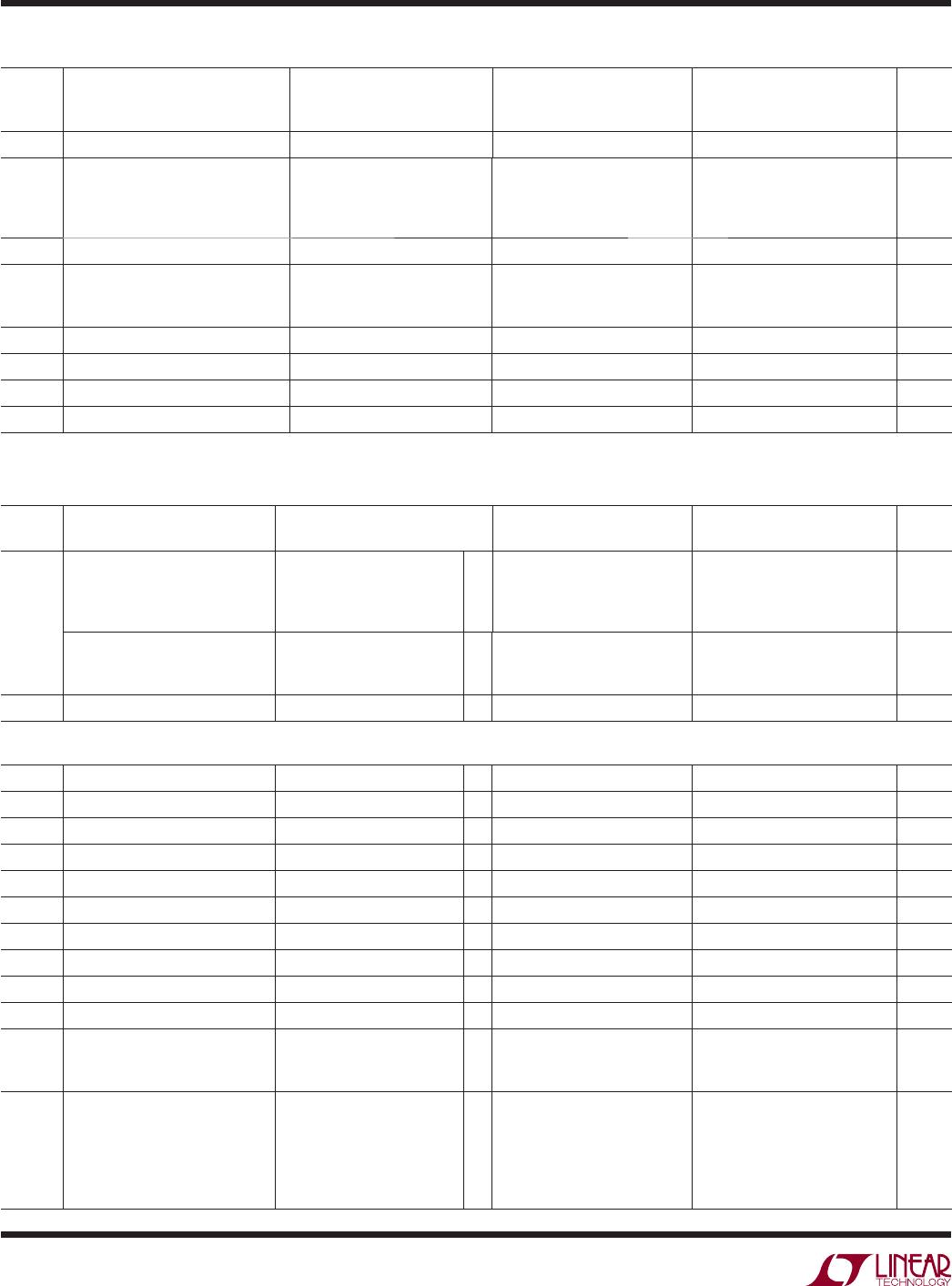
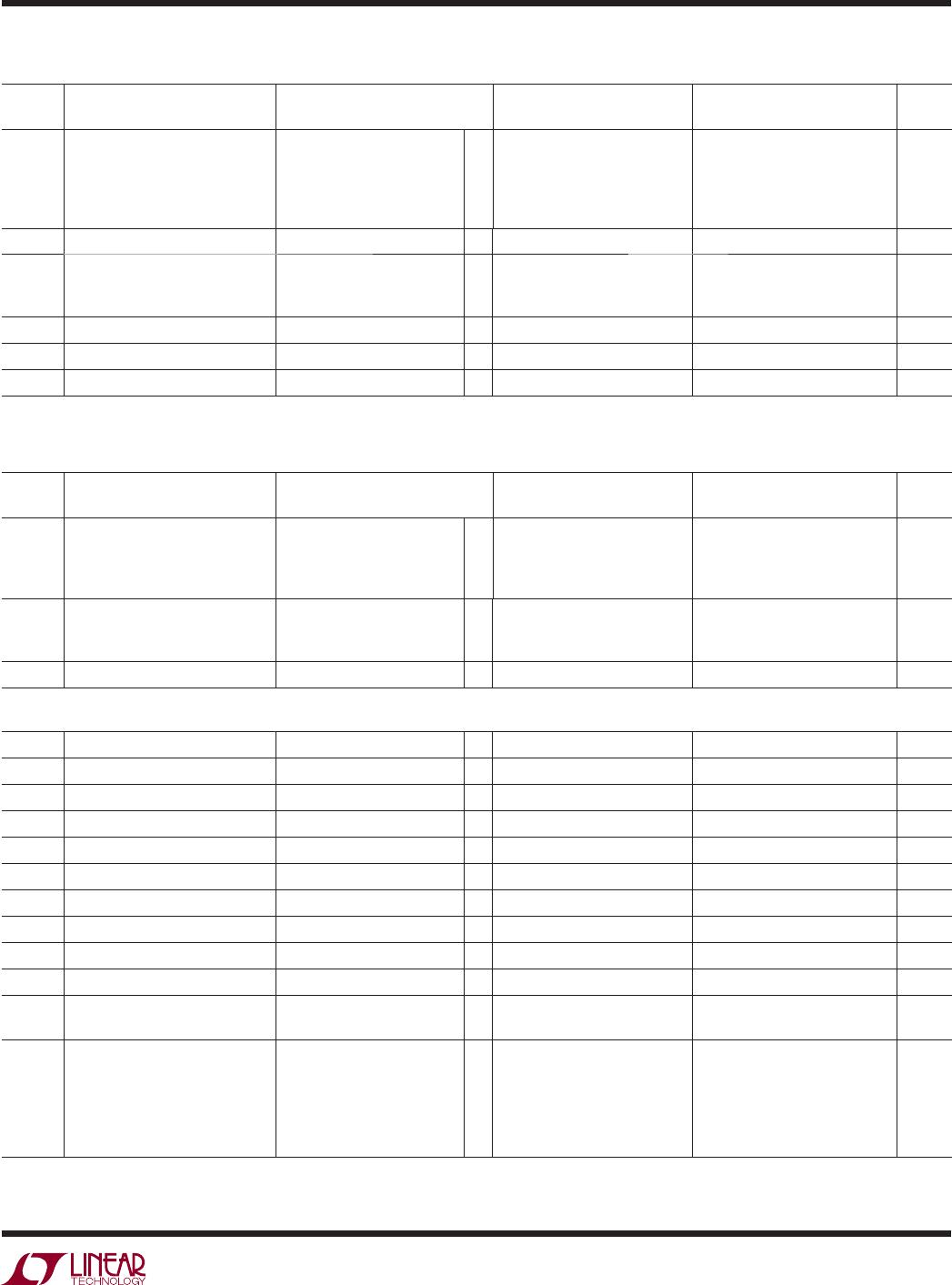
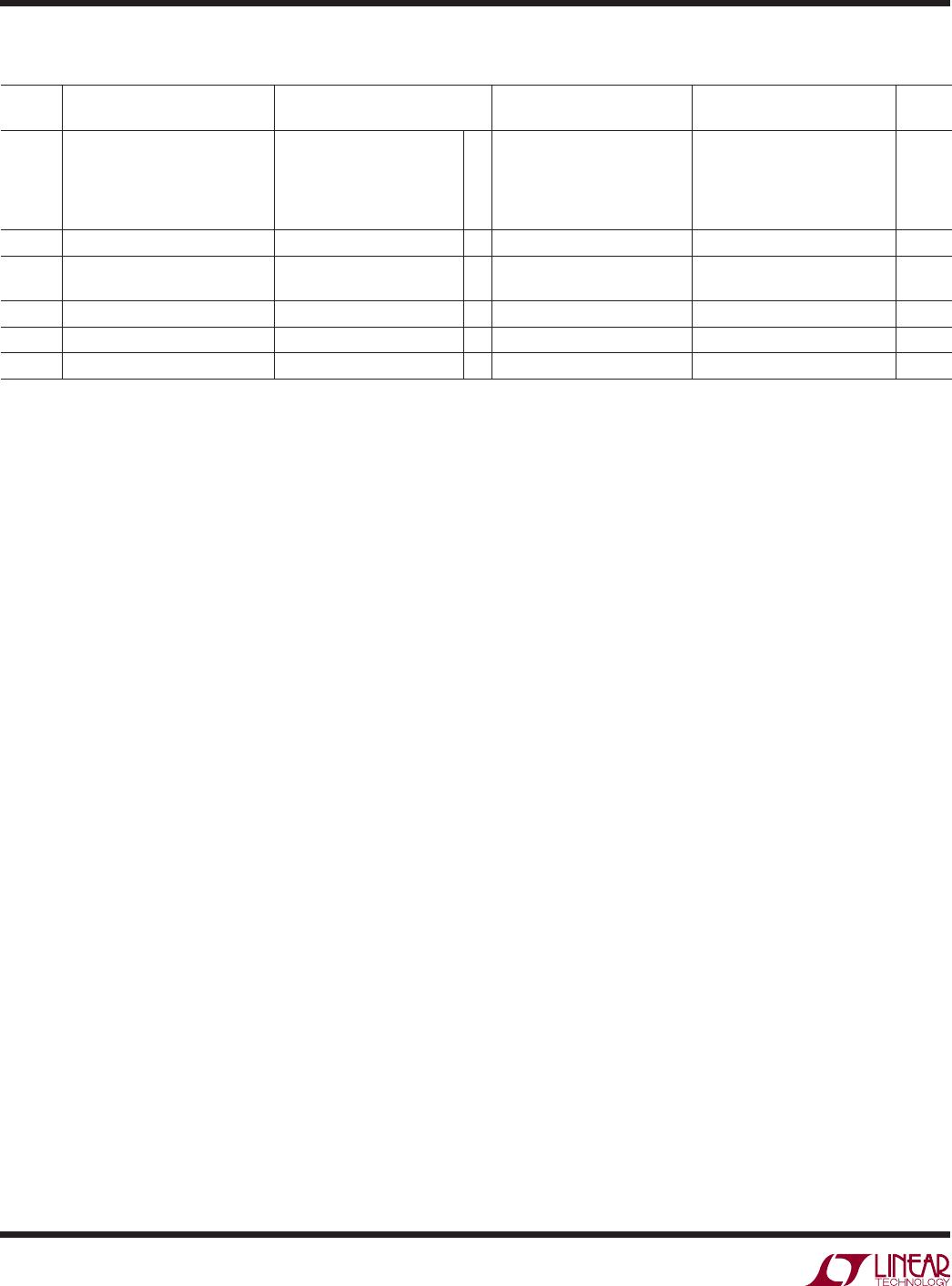
ELECTRICAL CHARACTERISTICS
The l denotes the specifications which apply over the full operating
temperature range, otherwise specifications are at T
A
= 25°C. V
S
= ±15V, V
CM
= 0V, 0°C ≤ T
A
≤ 70°C, R
L
= 2k, unless otherwise noted.
SYMBOL PARAMETER CONDITIONS (NOTE 7)
LT1167AI/LT1167AI-1 LT1167I/LT1167I-1
UNITSMIN TYP MAX MIN TYP MAX
PSRR Power Supply Rejection Ratio V
S
= ±2.3V to ±18V
G = 1
G = 10
G = 100
G = 1000
l
l
l
l
100
120
125
128
112
125
132
140
95
115
120
125
112
125
132
140
dB
dB
dB
dB
I
S
Supply Current
l
1.1 1.6 1.1 1.6 mA
V
OUT
Output Voltage Swing V
S
= ±2.3V to ±5V
V
S
= ±5V to ±18V
l
l
–V
S
+1.4
–V
S
+1.6
+V
S
–1.3
+V
S
–1.5
–V
S
+1.4
–V
S
+1.6
+V
S
–1.3
+V
S
–1.5
V
V
I
OUT
Output Current
l
15 20 15 20 mA
SR Slew Rate G = 1, V
OUT
= ±10V
l
0.55 0.95 0.55 0.95 V/μs
V
REF
REF Voltage Range (Note 3)
l
–V
S
+1.6 +V
S
–1.6 –V
S
+1.6 +V
S
–1.6 V
Note 1: Stresses beyond those listed under Absolute Maximum Ratings
may cause permanent damage to the device. Exposure to any Absolute
Maximum Rating condition for extended periods may affect device
reliability and lifetime.
Note 2: Does not include the effect of the external gain resistor RG.
Note 3: This parameter is not 100% tested.
Note 4: The LT1167AC/LT1167C/LT1167AC-1/LT1167C-1 are designed,
characterized and expected to meet the industrial temperature limits, but
are not tested at –40°C and 85°C. I-grade parts are guaranteed.
Note 5: This parameter is measured in a high speed automatic tester that
does not measure the thermal effects with longer time constants. The
magnitude of these thermal effects are dependent on the package used,
heat sinking and air flow conditions.
Note 6: Hysteresis in offset voltage is created by package stress that
differs depending on whether the IC was previously at a higher or lower
temperature. Offset voltage hysteresis is always measured at 25°C, but
the IC is cycled to 85°C I-grade (or 70°C C-grade) or –40°C I-grade
(0°C C-grade) before successive measurement. 60% of the parts will
pass the typical limit on the data sheet.
Note 7: Typical parameters are defined as the 60% of the yield parameter
distribution.
Note 8: Referred to input.