MAX6365–MAX6368
SOT23, Low-Power µP Supervisory Circuits
with Battery Backup and Chip-Enable Gating
10 ______________________________________________________________________________________
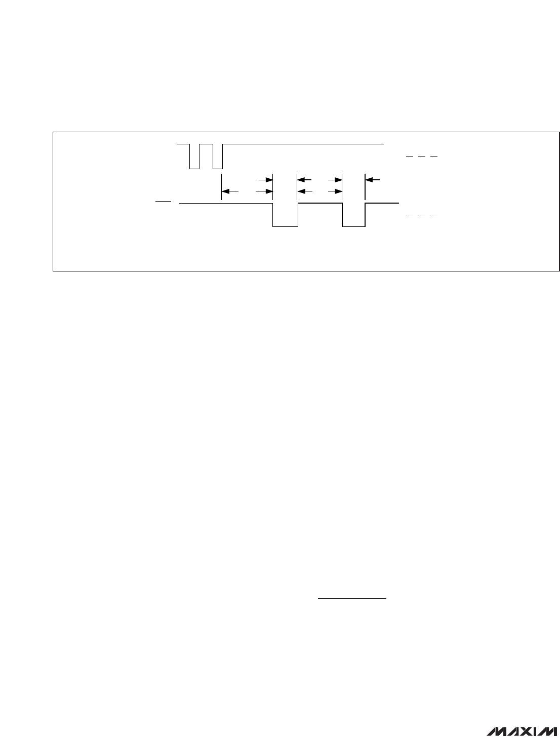
Watchdog Input (MAX6366 Only)
The watchdog monitors µP activity through the watch-
dog input (WDI). If the µP becomes inactive, reset
asserts. To use the watchdog function, connect WDI to
a bus line or µP I/O line. A change of state (high to low,
low to high, or a minimum 100ns pulse) resets the
watchdog timer. If WDI remains high or low for longer
than the watchdog timeout period (t
WD
), the internal
watchdog timer runs out and a reset pulse is triggered
for the reset timeout period (t
RP
). The internal watchdog
timer clears whenever reset asserts or whenever WDI
sees a rising or falling edge. If WDI remains in either a
high or low state, a reset pulse asserts periodically after
every t
WD
(Figure 2).
BATT ON Indicator (MAX6367 Only)
BATT ON is a push-pull output that drives high when in
battery-backup mode. BATT ON typically sinks 3.2mA
at 0.1V saturation voltage. In battery-backup mode, this
terminal sources approximately 10µA from OUT. Use
BATT ON to indicate battery-switchover status or to
supply base drive to an external pass transistor for
higher current applications (Figure 3).
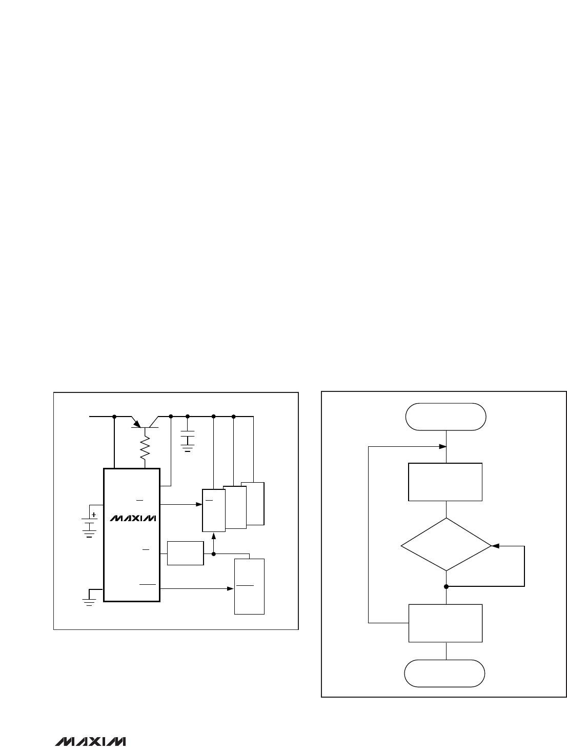
RESET IN Comparator (MAX6368 Only)
RESET IN is compared to an internal 1.235V reference.
If the voltage at RESET IN is less than 1.235V, reset
asserts. Use the RESET IN comparator as an undervolt-
age detector to signal a failing power supply or as a
secondary power-supply reset monitor.
To program the reset threshold (V
RTH
) of the secondary
power supply, use the following (see
Typical Operating
Circuit
):
V
RTH
= V
REF
(R1 / R2 + 1)
where V
REF
= 1.235V. To simplify the resistor selection,
choose a value for R2 and calculate R1:
R1 = R2 [(V
RTH
/ V
REF
) - 1]
Since the input current at RESET IN is 25nA (max),
large values (up to 1M) can be used for R2 with no
significant loss in accuracy. For example, in the
Typical
Operating Circuit
, the MAX6368 monitors two supply
voltages. To monitor the secondary 5V logic or analog
supply with a 4.60V nominal programmed reset thresh-
old, choose R2 = 100k, and calculate R1 = 273k.
Reset Output
A µP’s reset input starts the µP in a known state. The
MAX6365–MAX6368 µP supervisory circuits assert a
reset to prevent code-execution errors during power-
up, power-down, and brownout conditions. RESET is
guaranteed to be a logic low or logic high, depending
on the device chosen (see the
Ordering Information
).
RESET or RESET asserts when V
CC
is below the reset
threshold and for at least 150ms (t
RP
) after V
CC
rises
above the reset threshold. RESET or RESET also
asserts when MR is low (MAX6365) and when RESET IN
is less than 1.235V (MAX6368). The MAX6366 watch-
dog function will cause RESET (or RESET) to assert in
pulses following a watchdog timeout (Figure 2).
Applications Information
Operation Without
a Backup Power Source
The MAX6365–MAX6368 provide battery-backup func-
tions. If a backup power source is not used, connect
BATT to GND and OUT to V
CC
.
Figure 2. MAX6366 Watchdog Timeout Period and Reset Active Time
RESET
WDI
t
RP
t
RP
t
WD
t
WD
= WATCHDOG TIMEOUT PERIOD
t
RP
= RESET TIMEOUT PERIOD
t
WD
MAX6365–MAX6368
SOT23, Low-Power µP Supervisory Circuits
with Battery Backup and Chip-Enable Gating
______________________________________________________________________________________ 11
Watchdog Software Considerations
One way to help the watchdog timer monitor the soft-
ware execution more closely is to set and reset the
watchdog at different points in the program rather than
pulsing the watchdog input periodically. Figure 4
shows a flow diagram in which the I/O driving the
watchdog is set low in the beginning of the program,
set high at the beginning of every subroutine or loop,
and set low again when the program returns to the
beginning. If the program should hang in any subrou-
tine, the problem would be quickly corrected.
Replacing the Backup Battery
When V
CC
is above V
TH
, the backup power source can
be removed without danger of triggering a reset pulse.
The device does not enter battery-backup mode when
V
CC
stays above the reset threshold voltage.
Negative-Going V
CC
Transients
These supervisors are relatively immune to short-dura-
tion, negative-going V
CC
transients. Resetting the µP
when V
CC
experiences only small glitches is usually not
desirable.
The
Typical Operating Characteristics
section has a
Maximum Transient Duration vs. Reset Threshold
Overdrive graph for which reset is not asserted. The
graph was produced using negative-going V
CC
pulses,
starting at V
CC
and ending below the reset threshold by
the magnitude indicated (reset threshold overdrive).
The graph shows the maximum pulse width that a neg-
ative-going V
CC
transient can typically have without
triggering a reset pulse. As the amplitude of the tran-
sient increases (i.e., goes further below the reset
threshold), the maximum allowable pulse width
decreases. Typically, a V
CC
transient that goes 100mV
below the reset threshold and lasts for 30µs will not trig-
ger a reset pulse.
A 0.1µF bypass capacitor mounted close to the V
CC
pin provides additional transient immunity.
BATT
BATT ON
OUT
CMOS RAM
0.1µF
GND
RESET
CE IN
CE
RESET
CE OUT
MAX6367
V
CC
A0–A15
µP
+2.4V TO +5.5V
ADDRESS
DECODE
Figure 3. MAX6367 BATT ON Driving an External Pass
Transistor
Figure 4. Watchdog Flow Diagram
START
SET
WDI
LOW
RETURN
END
SUBROUTINE
OR PROGRAM LOOP
SET WDI
HIGH
MAX6365–MAX6368
SOT23, Low-Power µP Supervisory Circuits
with Battery Backup and Chip-Enable Gating
12 ______________________________________________________________________________________
RESET THRESHOLD RANGES (V)
SUFFIX
MIN TYP MAX
46 4.50 4.63 4.75
44 4.25 4.38 4.50
31 3.00 3.08 3.15
29 2.85 2.93 3.00
26 2.55 2.63 2.70
23 2.25 2.32 2.38
PART TOP MARK PART TOP MARK PART TOP MARK
MAX6365LKA23 AAAM MAX6366PKA23 AABK MAX6367HKA23 AACI
MAX6365LKA26 AAAL MAX6366PKA26 AABJ MAX6367HKA26 AACH
MAX6365LKA29* AAAK MAX6366PKA29* AABI MAX6367HKA29 AACG
MAX6365LKA31 AAAJ MAX6366PKA31 AABH MAX6367HKA31 AACF
MAX6365LKA44 AAAI MAX6366PKA44 AABG MAX6367HKA44 AACE
MAX6365LKA46* AAAH MAX6366PKA46* AABF MAX6367HKA46* AACD
MAX6365PKA23 AAAS MAX6366HKA23 AABQ MAX6368LKA23 AACO
MAX6365PKA26 AAAR MAX6366HKA26 AABP MAX6368LKA26 AACN
MAX6365PKA29* AAAQ MAX6366HKA29 AABO MAX6368LKA29* AACM
MAX6365PKA31 AAAP MAX6366HKA31 AABN MAX6368LKA31 AACL
MAX6365PKA44 AAAO MAX6366HKA44 AABM MAX6368LKA44 AACK
MAX6365PKA46* AAAN MAX6366HKA46* AABL MAX6368LKA46* AACJ
MAX6365HKA23 AAAY MAX6367LKA23 AABW MAX6368PKA23 AACU
MAX6365HKA26 AAAX MAX6367LKA26 AABV MAX6368PKA26 AACT
MAX6365HKA29 AAAW MAX6367LKA29* AABU MAX6368PKA29* AACS
MAX6365HKA31 AAAV MAX6367LKA31 AABT MAX6368PKA31 AACR
MAX6365HKA44 AAAU MAX6367LKA44 AABS MAX6368PKA44 AACQ
MAX6365HKA46* AAAT MAX6367LKA46* AABR MAX6368PKA46* AACP
MAX6366LKA23 AABE MAX6367PKA23 AACC MAX6368HKA23 AADA
MAX6366LKA26 AABD MAX6367PKA26 AACB MAX6368HKA26 AACZ
MAX6366LKA29* AABC MAX6367PKA29* AACA MAX6368HKA29 AACY
MAX6366LKA31 AABB MAX6367PKA31 AABZ MAX6368HKA31 AACX
MAX6366LKA44 AABA MAX6367PKA44 AABY MAX6368HKA44 AACW
MAX6366LKA46*
AAAZ
MAX6367PKA46*
AABX
MAX6368HKA46*
AACV
Reset Threshold Ranges
Device Marking Codes
*
These standard versions are available in small quantities through Maxim Distribution. Sample stock is generally held on
standard versions only. Contact factory for availability of nonstandard versions.

MAX6365LKA29+T

Mfr. #:
Manufacturer:
Maxim Integrated
Description:
Supervisory Circuits uPower Supervisor
Lifecycle:
New from this manufacturer.
Delivery:
DHL FedEx Ups TNT EMS
Payment:
T/T Paypal Visa MoneyGram Western Union