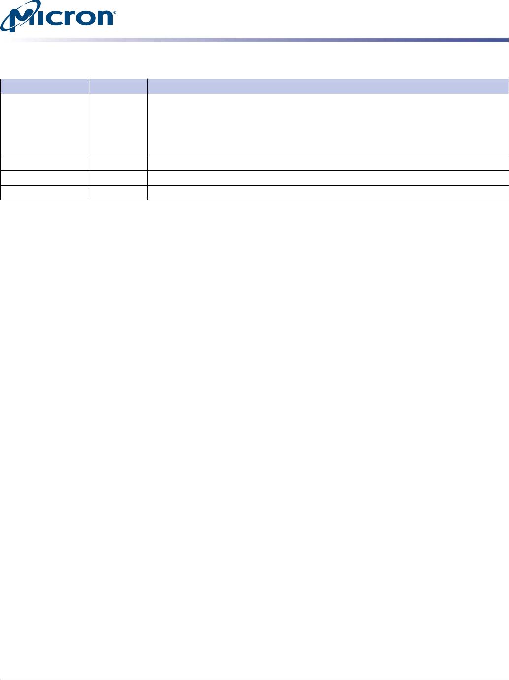
Table 5: Pin Descriptions (Continued)
Symbol Type Description
12V Supply Power supply for charging NVDIMM backup energy storage device (PowerGEM): 12V
±1.8V. Normal operation can be supported down to 6V; however, if these pins are be-
ing used to charge a PowerGEM, the charge time will be extended. Alternatively,
these pins can be a persistent power supply for NVDIMM during SAVE operation: 6V
to 13.8V.
RFU Reserved for future use.
NC No connect: No internal electrical connection is present.
NF No function: Internal connection may be present but has no function.
16GB (x72, ECC, SR) 288-Pin DDR4 Nonvolatile RDIMM
Pin Descriptions
CCMTD-1725822587-10375
asf18c2gx72pf1z.pdf - Rev. C 7/17 EN
10
Micron Technology, Inc. reserves the right to change products or specifications without notice.
© 2016 Micron Technology, Inc. All rights reserved.
DQ Map
Table 6: Component-to-Module DQ Map
Component
Reference
Number
Component
DQ Module DQ
Module Pin
Number
Component
Reference
Number
Component
DQ Module DQ
Module Pin
Number
U9 0 6 10 U10 0 14 21
1 4 3 1 12 14
2 7 155 2 15 166
3 5 148 3 13 159
U11 0 22 32 U12 0 30 43
1 20 25 1 28 36
2 23 177 2 31 188
3 21 170 3 29 181
U13 0 CB6 54 U16 0 39 247
1 CB4 47 1 36 95
2 CB7 199 2 38 102
3 CB5 192 3 37 240
U17 0 47 258 U18 0 55 269
1 44 106 1 52 117
2 46 113 2 54 124
3 45 251 3 53 262
U19 0 63 280 U26 0 57 275
1 60 128 1 59 282
2 62 135 2 56 130
3 61 273 3 58 137
U27 0 49 264 U28 0 41 253
1 51 271 1 43 260
2 48 119 2 40 108
3 50 126 3 42 115
U29 0 33 242 U32 0 CB0 49
1 35 249 1 CB3 201
2 32 97 2 CB1 194
3 34 104 3 CB2 56
U33 0 24 24 U34 0 16 27
1 27 27 1 19 179
2 25 25 2 17 172
3 26 26 3 18 34
U35 0 8 16 U36 0 0 5
1 11 168
1 3 157
2 9 161
2 1 150
3 10 23
3 2 12
16GB (x72, ECC, SR) 288-Pin DDR4 Nonvolatile RDIMM
DQ Map
CCMTD-1725822587-10375
asf18c2gx72pf1z.pdf - Rev. C 7/17 EN
11
Micron Technology, Inc. reserves the right to change products or specifications without notice.
© 2016 Micron Technology, Inc. All rights reserved.
Functional Block Diagram
Figure 3: Functional Block Diagram
DQ
DQ
DQ
DQ
ZQ
DQ0
DQ1
DQ2
DQ3
Vss
U36
DQ
DQ
DQ
DQ
ZQ
DQ4
DQ5
DQ6
DQ7
Vss
U9
DQS0_t
DQS0_c
DQS9_t
DQS9_c
DQ
DQ
DQ
DQ
ZQ
DQ8
DQ9
DQ10
DQ11
Vss
U35
DQ
DQ
DQ
DQ
ZQ
DQ12
DQ13
DQ14
DQ15
Vss
U10
DQS1_t
DQS1_c
DQS10_t
DQS10_c
DQ
DQ
DQ
DQ
ZQ
DQ16
DQ17
DQ18
DQ19
Vss
U34
DQ
DQ
DQ
DQ
ZQ
DQ20
DQ21
DQ22
DQ23
Vss
U11
DQS2_t
DQS2_c
DQS11_t
DQS11_c
DQ
DQ
DQ
DQ
ZQ
DQ24
DQ25
DQ26
DQ27
Vss
U33
DQ
DQ
DQ
DQ
ZQ
DQ28
DQ29
DQ30
DQ31
Vss
U12
DQS3_t
DQS3_c
DQS12_t
DQS12_c
DQ
DQ
DQ
DQ
ZQ
CB0
CB1
CB2
CB3
Vss
U32
DQ
DQ
DQ
DQ
ZQ
CB4
CB5
CB6
CB7
Vss
U13
DQS8_t
DQS8_c
DQS17_t
DQS17_c
DQ
DQ
DQ
DQ
ZQ
DQ32
DQ33
DQ34
DQ35
Vss
U29
DQ
DQ
DQ
DQ
ZQ
DQ36
DQ37
DQ38
DQ39
Vss
U16
DQS4_t
DQS4_c
DQS13_t
DQS13_c
DQ
DQ
DQ
DQ
ZQ
DQ40
DQ41
DQ42
DQ43
Vss
U28
DQ
DQ
DQ
DQ
ZQ
DQ44
DQ45
DQ46
DQ47
Vss
U17
DQS5_t
DQS5_c
DQS14_t
DQS14_c
DQ
DQ
DQ
DQ
ZQ
DQ48
DQ49
DQ50
DQ51
Vss
U27
DQ
DQ
DQ
DQ
ZQ
DQ52
DQ53
DQ54
DQ55
Vss
U18
DQS6_t
DQS6_c
DQS15_t
DQS15_c
DQ
DQ
DQ
DQ
ZQ
DQ56
DQ57
DQ58
DQ59
Vss
U26
DQ
DQ
DQ
DQ
ZQ
DQ60
DQ61
DQ62
DQ63
Vss
U19
DQS7_t
DQS7_c
DQS16_t
DQS16_c
A/B-CS0_n
U15
A/B-CS0_n, A/B-BA[1:0]A/B-BG[1:0],
A/B-ACT_n, A/B-A[17, 13:0], A/B-RAS_n/A16,
A/B-CAS_n/A15, A/B-WE_n/A14,
A/B-CKE0, A/B-ODT0
CK[1:0]_t
CK[1:0]_c
Command, control, address, and clock line terminations:
DDR4
SDRAM
VTT
DDR4
SDRAM
VDD
U5
A0
SPD EEPROM/
Temperature
sensor
A1 A2
SA0
SA1
SDA
SCL
EVT
EVENT_n
CS_n DQS_t DQS_c
CS_n DQS_t DQS_c
CS_n DQS_t DQS_c
CS_n DQS_t DQS_c
CS_n DQS_t DQS_c
CS_n DQS_t DQS_c
CS_n DQS_t DQS_c
CS_n DQS_t DQS_c
CS_n DQS_t DQS_c
CS_n DQS_t DQS_c
CS_n DQS_t DQS_c
CS_n DQS_t DQS_c
CS_n DQS_t DQS_c
CS_n DQS_t DQS_c
CS_n DQS_t DQS_c
CS_n DQS_t DQS_c
CS_n DQS_t DQS_c
CS_n DQS_t DQS_c
SA2
VREFCA
VSS
DDR4 SDRAM, Register
VDD
Control, command and
address termination
VDDSPD
SPD EEPROM/Temp Sensor,
Register
VTT
DDR4 SDRAM, Register
DDR4 SDRAM
VPP
CS0_n
BA[1:0]
BG[1:0]
ACT_n
A[17, 13:0]
RAS_n/A16
CAS_n/A15
WE_n/A14
CKE0
ODT0
PAR_IN
ALERT_CONN_N
A/B-CS0_n: Rank 0
A/B-BA[1:0]: DDR4 SDRAM
A/B-BG[1:0]: DDR4 SDRAM
A/B-ACT_n: DDR4 SDRAM
A/B-A[17,13:0]: DDR4 SDRAM
A/B-RAS_n/A16: DDR4 SDRAM
A/B-CAS_n/A15: DDR4 SDRAM
A/B-WE_n/A14: DDR4 SDRAM
A/B-CKE0: Rank 0
A/B-ODT0: Rank 0
A/B-PAR: DDR4 SDRAM
ALERT_DRAM: DDR4 SDRAM
R
E
G
I
S
T
E
R
&
P
L
L
RESET_N
CK[1:0]_c
DDR4 SDRAM
QRST_N: DDR4 SDRAM
CK[1:0]_t
ZQ
VSS
SA0
SA1
SA2
SCL
SDA
CK0_t
CK0_c
CK1_t
CK1_c
Note:
1. The ZQ ball on each DDR4 component is connected to an external 240Ω ±1% resistor
that is tied to ground. It is used for the calibration of the component’s ODT and output
driver.
16GB (x72, ECC, SR) 288-Pin DDR4 Nonvolatile RDIMM
Functional Block Diagram
CCMTD-1725822587-10375
asf18c2gx72pf1z.pdf - Rev. C 7/17 EN
12
Micron Technology, Inc. reserves the right to change products or specifications without notice.
© 2016 Micron Technology, Inc. All rights reserved.

MTA18ASF2G72PF1Z-2G6V21AB

Mfr. #:
Manufacturer:
Micron
Description:
Memory Modules DDR4 NVDIMM 16GB NVRDIMM-N NA
Lifecycle:
New from this manufacturer.
Delivery:
DHL FedEx Ups TNT EMS
Payment:
T/T Paypal Visa MoneyGram Western Union

Products related to this Datasheet