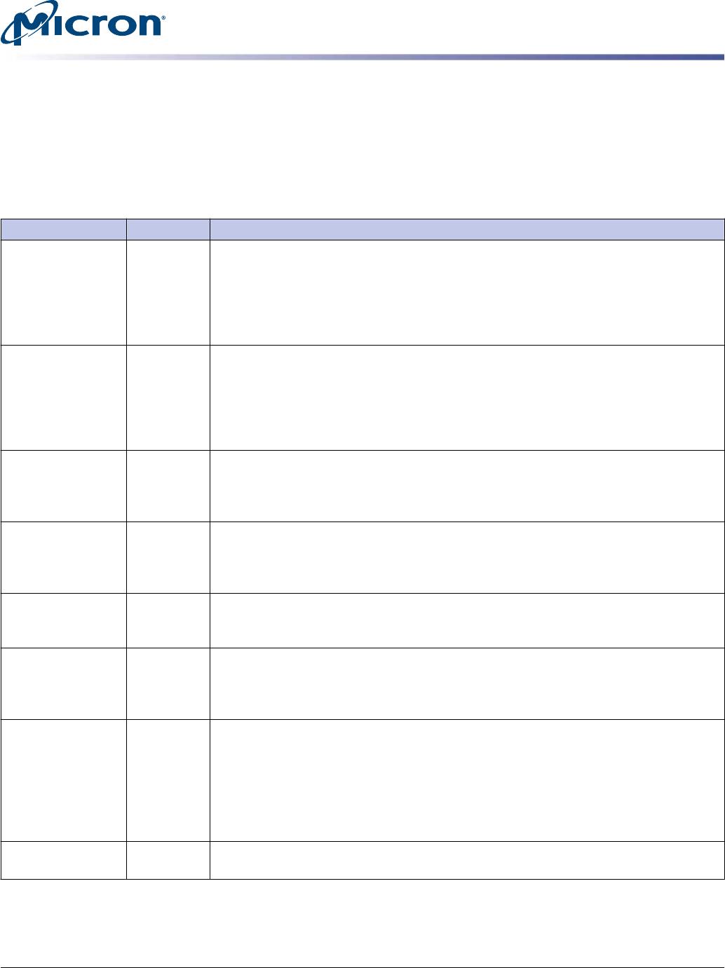
Table 5: Pin Descriptions (Continued)
Symbol Type Description
CKEx Input Clock enable: CKE HIGH activates, and CKE LOW deactivates, the internal clock sig-
nals, device input buffers, and output drivers. Taking CKE LOW provides PRECHARGE
POWER-DOWN and SELF REFRESH operations (all banks idle), or active power-down
(row active in any bank). CKE is asynchronous for self refresh exit. After V
REFCA
has be-
come stable during the power-on and initialization sequence, it must be maintained
during all operations (including SELF REFRESH). CKE must be held HIGH throughout
read and write accesses. Input buffers (excluding CK_t, CK_c, ODT, RESET_n, and CKE)
are disabled during power-down. Input buffers (excluding CKE and RESET_n) are disa-
bled during self refresh.
CSx_n Input Chip select: All commands are masked when CS_n is registered HIGH. CS_n provides
external rank selection on systems with multiple ranks. CS_n is considered part of the
command code. CS2_n and CS3_n are not used on UDIMMs.
ODTx Input On-die termination: ODT (registered HIGH) enables termination resistance internal
to the DDR4 SDRAM. When ODT is enabled, on-die termination (R
TT
) is applied only to
each DQ, DQS_t, DQS_c, DM_n/DBI_n/TDQS_t, and TDQS_c signal for x4 and x8 config-
urations (when the TDQS function is enabled via the mode register). For the x16 con-
figuration, R
TT
is applied to each DQ, DQSU_t, DQSU_c, DQSL_t, DQSL_c, UDM_n, and
LDM_n signal. The ODT pin will be ignored if the mode registers are programmed to
disable R
TT
.
PARITY Input Parity for command and address: This function can be enabled or disabled via the
mode register. When enabled in MR5, then DRAM calculates Parity with ACT_n,
RAS_n/A16, CAS_n/A15, WE_n/A14, BG[1:0], BA[1:0], A[16:0]. Input parity should be
maintained at the rising edge of the clock and at the same time with command and
address with CS_n LOW.
RAS_n/A16
CAS_n/A15
WE_n/A14
Input Command inputs: RAS_n/A16, CAS_n/A15, and WE_n/A14 (along with CS_n) define
the command and/or address being entered. Those pins have multifunction. For exam-
ple, for activation with ACT_n LOW, these are addresses like A16, A15, and A14, but
for a non-activation command with ACT_n HIGH, these are command pins for READ,
WRITE, and other commands defined in the command truth table.
RESET_n CMOS Input Active LOW asynchronous reset: Reset is active when RESET_n is LOW; inactive
when RESET_n is HIGH. RESET_n must be HIGH during normal operation. RESET_n is
blocked when NVDIMM is armed.
SAx Input
Serial address inputs: Used to configure the temperature sensor/SPD EEPROM ad-
dress range on the I
2
C bus.
SCL Input
Serial clock for temperature sensor/SPD EEPROM: Used to synchronize communi-
cation to and from the temperature sensor/SPD EEPROM on the I
2
C bus.
DQx, CBx I/O Data input/output and Check Bit input/output : Bidirectional data bus. DQ repre-
sents DQ[3:0], DQ[7:0], and DQ[15:0] for the x4, x8, and x16 configurations, respec-
tively. If cyclic redundancy checksum (CRC) is enabled via the mode register, then CRC
code is added at the end of the data burst. Either one or all of DQ0, DQ1, DQ2, or
DQ3 is/are used for monitoring the internal V
REF
level during test via mode register
setting MR[4] A[4] = HIGH; training times change when enabled.
16GB (x72, ECC, SR) 288-Pin DDR4 Nonvolatile RDIMM
Pin Descriptions
CCMTD-1725822587-10375
asf18c2gx72pf1z.pdf - Rev. C 7/17 EN
8
Micron Technology, Inc. reserves the right to change products or specifications without notice.
© 2016 Micron Technology, Inc. All rights reserved.