AMIS−49587
www.onsemi.com
34
7 DETAILED SOFTWARE DESCRIPTION
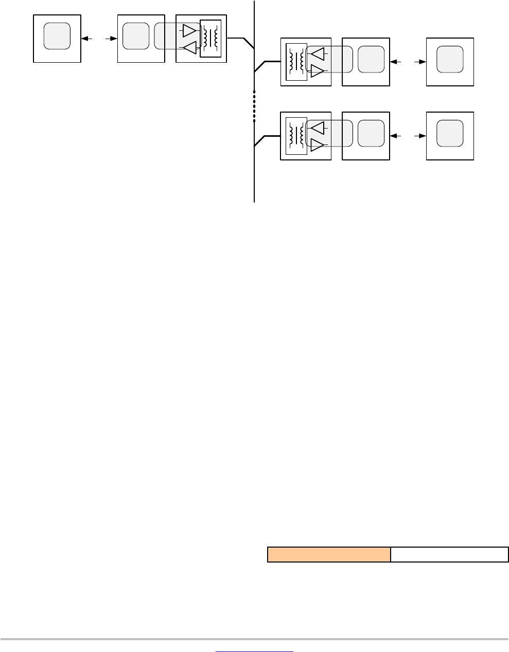
Figure 29 depicts a typical PLC network with one master and 2 slaves. Each AMIS−49587 is controlled by an external CPU
over a RS232 interface. See paragraph Serial Communication Interface Physical Layer Description for a description on
hardware signals and timings.
Figure 29. Typical PLC Network Architecture
AMIS49587 External CPU
RS232
AFE
MAC
layer
LCC
layer
PLC Slave or Server
AMIS49587 External CPU
RS232
AFE
MAC
layer
LCC
layer
PLC Slave or Server
AMIS49587External CPU
RS232
MAC
layer
LCC
layer
PLC Master or Client
Power Line
AFE
Physical
Layer
Physical
Layer
Physical
Layer
This document describes how the RS232 frames need to be
composed to:
Get status information from the AMIS−49587
Configure the AMIS−49587
Send and Receive network data with the
AMIS−49587
Get performance and data path statistics from
AMIS−49587
7.1 CONFIGURE THE AMIS−49587
The AMIS−49587 can operate in different configurations:
Master or Client configuration: A Master is a client
to the data served by one or many slaves on the
power line. It collects data from and controls the
slave devices.
Slave or Server configuration: A Slave is a server of
the data to the Master.
Spy or Monitor configuration: Spy or Monitor mode
is used to only listen to the data that comes across
the power line. Only the physical layer frame
correctness is checked (preamble and SSD, see
Figure 34 Power Line Data Frame Structure). When
the frame is correct, it is passed to the external
processor.
Not set configuration: No valid configuration
command has been passed to the AMIS−49587 after
reset. No power line communication is possible.
This is the state of the AMIS−49587 after a
hardware reset or after a reset command has been
sent to it.
Each mode has its own configuration parameters and
subset of commands.
7.2 OBTAINING STATUS MESSAGES
Opposite to all other commands over the serial interface,
the status message is retrieved from the AMIS−49587 by a
hardware event only. To get the status message the serial
driver on the external CPU needs to pull the T_REQ HW pin
low, like described in paragraph Serial Communication
Interface Physical Layer Description.
Whenever the external controller sends a command to the
AMIS−49587, the T_REQ HW pin should be pulled low to
get a new status message from the MODEM. Only when the
status message indicates that the buffer is not busy, the
command may be send. The AMIS49587 is the master on
the serial interface and needs to be queried to get access to
the bus.
The format of the status message depends on the active
configuration of the AMIS−49587 (not set, slave, master or
monitor).
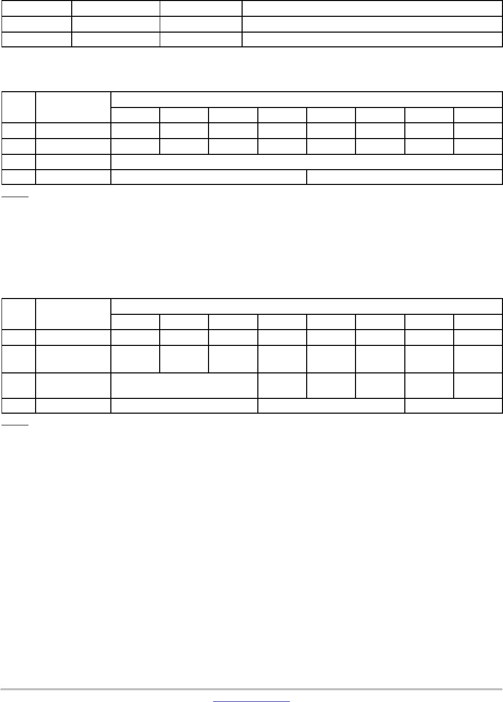
Table 35. SERIAL PORT STATUS FRAME LAYOUT
START Status_Data
AMIS−49587
www.onsemi.com
35
Table 36.
Field Byte Length Value Description
START 1 3Fh Character (”?”), indicating start of status message.
Status_Data 4 Byte String 4 bytes encoding different status bits
Important: Frame in little endian format (LSByte first)
STATUS MESSAGE IN NOT SET MODE
Byte Content
Structure
Bit 7 Bit 6 Bit 5 Bit 4 Bit 3 Bit 2 Bit 1 Bit 0
1 Start 0 1 1 1 1 1 1 1
2 Data 1 x x x x x x Not SET X
3 Data 2 RSV[7:0]
4 Data 3 SVN[7:4] SVN[3:0]
Where:
Not SET Indicates if AMIS−49587 has received a valid configuration
RSV[7:0] Reserved
SVN[7:4] Software Version Number: major release
SVN[3:0] Software Version Number: minor release
x Not Used
7.2.1 Status Message in SLAVE or SERVER MODE:
STATUS MESSAGE IN SLAVE MODE
Byte Content
Structure
Bit 7 Bit 6 Bit 5 Bit 4 Bit 3 Bit 2 Bit 1 Bit 0
1 Start 0 1 1 1 1 1 1 1
2 Data 1 x x x Not
LOCKED
NEW Not SYNC Not
SET
Buffer
BUSY
3 Data 2 TS_Nb[2:0] x x x ALARM
_EN
PLL
_LOCK
4 Data 3 DEP[2:0] MDC[2:0] REP[1:0]
Where:
Not LOCKED Indication if AMIS 4958x is Unlocked
NEW Indication if AMIS 4958x is New
Not SYNC Indication of synchronization with mains
Not SET Indicates if AMIS−49587 has received a valid configuration
Buffer BUSY Indication if PLC buffer is busy
TS_Nb[2:0] Time slot counter
Alarm_EN Alarm detection status
PLL_LOCK PLL lock status
DEP[2:0] Delta Electrical Phase
MDC[2:0] Minimum Delta Credit Value
REP[1:0] Repeater Mode
x Not Used
AMIS−49587
www.onsemi.com
36
7.2.2 Status Message in MASTER or CLIENT MODE:
STATUS MESSAGE IN SLAVE MODE
Byte Content
Structure
Bit 7 Bit 6 Bit 5 Bit 4 Bit 3 Bit 2 Bit 1 Bit 0
1 Start 0 1 1 1 1 1 1 1
2 Data 1 x x x x x Not SYNC Not
SET
Buffer
BUSY
3 Data 2 TS_Nb[2:0] x x x ALARM
_EN
PLL
_LOCK
4 Data 3 InvalFrCnt[7:0]
Where:
Not SYNC Indication of synchronization with mains
Not SET Indicates if AMIS−49587 has received a valid configuration
Buffer BUSY Indication if PLC buffer is busy
TS_Nb[2:0] Time slot counter
Alarm_EN Alarm detection status
PLL_LOCK PLL lock status
InvalFrCnt[7:0] Invalid Frame counter
x Not Used
7.2.3 Status Message in MONITOR MODE:
STATUS MESSAGE IN SLAVE MODE
Byte Content
Structure
Bit 7 Bit 6 Bit 5 Bit 4 Bit 3 Bit 2 Bit 1 Bit 0
1 Start 0 1 1 1 1 1 1 1
2 Data 1 x x x x x Not SYNC Not SET Buffer
BUSY
3 Data 2 TS_Nb[2:0] x x x ALARM
_EN
PLL
_LOCK
4 Data 3 DEP[2:0] x x x x x
Where:
Not SYNC Indication of synchronization with mains
Not SET Indicates if AMIS−49587 has received a valid configuration
Buffer BUSY Indication if PLC buffer is busy
TS_Nb[2:0] Time slot counter
Alarm_EN Alarm detection status
PLL_LOCK PLL lock status
DEP[2:0] Delta Electrical Phase
x Not Used
7.3 CONFIGURATION OF THE AMIS−49587
The serial port frame format is the same for RX and TX and is different from the status data frames.
Table 37. SERIAL PORT CONFIGURATION AND DATA PATH FRAME LAYOUT
<STX> Length Command User_Data CHK

AMIS49587C5871G

Mfr. #:
Manufacturer:
ON Semiconductor
Description:
Network Controller & Processor ICs C587- NAF- AMIS49587
Lifecycle:
New from this manufacturer.
Delivery:
DHL FedEx Ups TNT EMS
Payment:
T/T Paypal Visa MoneyGram Western Union