Spec No.JELF243A-0050AA-01 P.10/14
MURATA MFG.CO.,LTD
Reference Only
11.2 Flux, Solder
Use rosin-based flux.
Includes middle activator equivalent to 0.06(wt)% to 0.1(wt) % Chlorine.
Don’t use highly acidic flux with halide content exceeding 0.2(wt) % (chlorine conversion value).
Don’t use water-soluble flux.
Use Sn-3.0Ag-0.5Cu solder.
Standard thickness of solder paste : 100μm to 150μm.
11.3 Reflow soldering conditions
Pre-heating should be in such a way that the temperature difference between solder and product
surface is limited to 150°C max. Cooling into solvent after soldering also should be in such a way
that the temperature difference is limited to 100°C max.
Insufficient pre-heating may cause cracks on the product, resulting in the deterioration of products
quality.
Standard soldering profile and the limit soldering profile is as follows.
The excessive limit soldering conditions may cause leaching of the electrode and / or resulting
in the deterioration of product quality.
Reflow soldering profile
Standard Profile Limit Profile
Pre-heating 150°C180°C 90s±30s
Heating above 220°C30s60s above 230°C60s max.
Peak temperature 245°C±3°C 260°C,10s
Cycle of reflow 2 times 2 times
11.4 Reworking with soldering iron
The following conditions must be strictly followed when using a soldering iron.
Pre-heating 150°C,1 min
Tip temperature 350°C max.
Soldering iron output 80W max.
Tip diameter φ3mm max.
Soldering time 3(+1,-0)s
Time 2 times
Note :Do not directly touch the products with the tip of the soldering iron in order to prevent the
crack on the products due to the thermal shock.
11.5 Solder Volume
Solder shall be used not to be exceeded the upper limits as shown below.
Accordingly increasing the solder volume, the mechanical stress to Chip is also increased.
Exceeding solder volume may cause the failure of mechanical or electrical performance.
1/3T
tT
T
thickness of product
Limit Profile
Standard Profile
90s±30s
230
260℃
245℃±3
220
30s~60s
60s max.
180
150
Temp.
(s)
(℃)
Time.
Recommendable(t)
Upper Limit
T
Recommendable(t)
Upper Limit
T
Spec No.JELF243A-0050AA-01 P.11/14
MURATA MFG.CO.,LTD
Reference Only
11.6 Product’s location
The following shall be considered when designing and laying out P.C.B.'s.
(1) P.C.B. shall be designed so that products are not subject to the mechanical stress due to
warping the board.
Products direction
Products shall be located in the sideways
direction (Length:a
b) to the mechanical
stress.
(2) Components location on P.C.B. separation.
It is effective to implement the following measures, to reduce stress in separating the board.
It is best to implement all of the following three measures; however, implement as many measures as possible
to reduce stress.
Contents of Measures Stress Level
(1) Turn the mounting direction of the component parallel to the board separation surface. A > D *1
(2) Add slits in the board separation part. A > B
(3) Keep the mounting position of the component away from the board separation surface. A > C
*1 A > D is valid when stress is added vertically to the perforation as with Hand Separation.
If a Cutting Disc is used, stress will be diagonal to the PCB, therefore A > D is invalid.
(3) Mounting Components Near Screw Holes
When a component is mounted near a screw hole, it may be affected by the board deflection that occurs during
the tightening of the screw. Mount the component in a position as far away from the screw holes as possible.
Poor example
Good example
b
a
Seam
Slit
A
D
B
C
b
a
Length:a
<
b
Spec No.JELF243A-0050AA-01 P.12/14
MURATA MFG.CO.,LTD
Reference Only
11.7 Cleaning Conditions
Products shall be cleaned on the following conditions.
(1) Cleaning temperature shall be limited to 60°C max.(40°C max for IPA)
(2) Ultrasonic cleaning shall comply with the following conditions with avoiding the resonance
phenomenon at the mounted products and P.C.B.
Power : 20 W / l max. Frequency : 28kHz to 40kHz Time : 5 min max.
(3) Cleaner
1. Alcohol type cleaner
Isopropyl alcohol (IPA)
2. Aqueous agent
PINE ALPHA ST-100S
(4) There shall be no residual flux and residual cleaner after cleaning.
In the case of using aqueous agent, products shall be dried completely after rinse with de-ionized
water in order to remove the cleaner.
(5) Other cleaning Please contact us.
11.8 Resin coating
The inductance value may change due to high cure-stress of resin to be used for coating/molding products.
An open circuit issue may occur by mechanical stress caused by the resin, amount/cured shape of resin,
or operating condition etc. Some resin contains some impurities or chloride possible to generate chlorine
by hydrolysis under some operating condition may cause corrosion of wire of coil, leading to open circuit.
So, please pay your careful attention when you select resin in case of coating/molding the products with the resin.
Prior to use the coating resin, please make sure no reliability issue is observed by evaluating products mounted
on your board.
11.9 Caution for use
Sharp material such as a pair of tweezers or other material such as bristles of cleaning brush , shall not be touched
to the winding portion to prevent the
breaking of wire.
Mechanical shock should not be applied to the products mounted on the board to prevent the breaking of the core.
11.10 Notice of product handling at mounting
In some mounting machines,when picking up components support pin pushes up the components from the
bottom of base tape. In this case, please remove the support pin. The support pin may damage the
components and break wire.
In rare case ,the laser recognition can not recognize this component. Please contact us when you use laser
recognition. (There is no problem with the permeation and reflection type.)
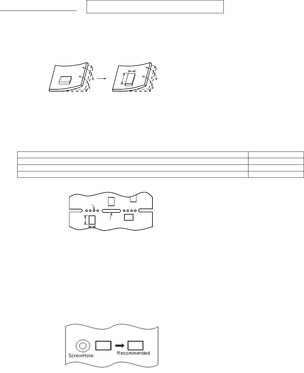
11.11 Handling of a substrate
After mounting products on a substrate, do not apply any stress to the product caused by bending or twisting to the
substrate when cropping the substrate, inserting and removing a connector from the substrate or tightening screw to
the substrate.
Excessive mechanical stress may cause cracking in the product.
Bending Twisting

LQW15AN4N3B00D

Mfr. #:
Manufacturer:
Murata Electronics
Description:
Fixed Inductors 4.3 NH +-.1NH
Lifecycle:
New from this manufacturer.
Delivery:
DHL FedEx Ups TNT EMS
Payment:
T/T Paypal Visa MoneyGram Western Union