Spec No.JELF243A-0050AA-01 P.7/14
MURATA MFG.CO.,LTD
Reference Only
No. Item Specification Test Method
7.3 Vibration Chip coil shall not be damaged
after tested as test method.
Oscillation Frequency:
10Hz~55Hz~10Hz for 1 min
Total Amplitude:1.5mm
Testing Time:
A period of 2 hours in each of mutually
perpendicular directions.
7.4 Solderability The wetting area of the electrode
shall be at least 90% covered with
new solder coating.
Flux:Ethanol solution of rosin,25(wt)%
Includes activator equivalent to 0.06(wt)%
chlorine.(immersed for 5s to 10s)
Solder:Sn-3.0Ag-0.5Cu
Pre-Heating:150°C±10°C / 60s to 90s
Solder Temperature:240°C±5°C
Immersion Time:3s±1s
7.5 Resistance to
Soldering Heat
Appearance:No damage
Inductance Change: within ±5%
Flux:Ethanol solution of rosin,25(wt)%
Includes activator equivalent to 0.06(wt)%
Chlorine.(immersed for 5s to 10s)
Solder:Sn-3.0Ag-0.5Cu
Pre-Heating:150°C±10°C / 60s to 90s
Solder Temperature:270°C±5°C
Immersion Time:10s±1s
Then measured after exposure in the room
condition for 24h±2h.
8.Environmental Performance
It shall be soldered on the substrate.
No. Item Specification Test Method
8.1 Heat Resistance Appearance:No damage
Inductance Change: within ±5%
Q Change: within ±20%
Temperature:125°C±2°C
Time:1000h (+48h,0h)
Then measured after exposure in the room
condition for 24h±2h.
8.2 Cold Resistance Temperature:-55°C±2°C
Time:1000h (+48h,-0h)
Then measured after exposure in the room
condition for 24h±2 h.
8.3 Humidity Temperature:70°C±2°C
Humidity:90%(RH) to 95%(RH)
Time:1000h (+48h,-0h)
Then measured after exposure in the room
condition for 24h±2h.
8.4 Temperature
Cycle
1 cycle:
1 step:-55°C±2°C / 30min±3 min
2 step:Ordinary temp. / 10min to 15 min
3 step:+125°C±2°C / 30min±3 min
4 step:Ordinary temp. / 10min to15 min
Total of 10 cycles
Then measured after exposure in the room
condition for 24h±2h.
Spec No.JELF243A-0050AA-01 P.8/14
MURATA MFG.CO.,LTD
Reference Only
9.Specification of Packaging
9.1 Appearance and Dimensions of paper tape
(8mm-wide)
(in mm)
Inductance
A*
(mm)
(Tolerance ±0.03)
B* (mm)
(Tolerance ±0.03)
1N5, 2N42N8, 3N94N8, 5N86N8, 8N29N9, 11N, 12N, 15N 0.69 1.18
1N61N8, 2N9, 3N0, 3N1, 3N2, 4N95N1, 6N9-7N5, 10N, 13N,
16N
23N, R10, R12
0.66 1.18
24N91N 0.64 1.18
Typical value
9.2 Specification of Taping
(1) Packing quantity (standard quantity)
10,000 pcs. / reel
(2) Packing Method
Products shall be packed in the cavity of the base tape and sealed by Cover tape.
(3) Sprocket hole
The sprocket holes are to the right as the tape is pulled toward the user.
(4) Spliced point
Base tape and Cover tape has no spliced point.
(5) Missing components number
Missing components number within 0.1% of the number per reel or 1 pc., whichever is greater,
and are not continuous. The Specified quantity per reel is kept.
9.3 Pull Strength
Cover tape 5N min.
9.4 Peeling off force of cover tape
Speed of Peeling off 300mm/min
Peeling off force
0.1 to 0.6N
(minimum value is typical)
9.5 Dimensions of Leader-tape,Trailer and Reel
There shall be leader-tape ( cover tape and empty tape) and trailer-tape (empty tape) as follows.
(in mm)
F
Cover tape
Base tape
165
°
to 180
Empty tape
190 min.
Leader
Trailer
2.0±0.5
φ
13.0±0.2
φ
21.0±0.8
φ
180
φ
60
9.0
13.0±1.4
+1
-
0
+0
-3
Direction of feed
210 min.
160 min.
Cover tape
+1
-0
Label
A
1.18±0.03
2.0±0.05
2.0±0.05
4.0±0.1
φ
1.
3.5±0.05
8.0±0.2
0.8 max.
0.1
0
1.75±0.1
Direction of feed
B
Spec No.JELF243A-0050AA-01 P.9/14
MURATA MFG.CO.,LTD
Reference Only
9.6 Marking for reel
Customer part number, MURATA part number, Inspection number(
1) ,RoHS Marking(2),
Quantity etc
・・・
1) <Expression of Inspection No.> □□ OOOO ×××
(1) (2) (3)
(1) Factory Code
(2) Date First digit : Year / Last digit of year
Second digit : Month / Jan. to Sep.
1 to 9, Oct. to Dec. O, N, D
Third, Fourth digit : Day
(3) Serial No.
2) <Expression of RoHS Marking > ROHS Y ()
(1) (2)
(1)
RoHS regulation conformity parts.
(2) MURATA classification number
9.7 Marking for Outside package (corrugated paper box)
Customer name, Purchasing order number, Customer part number, MURATA part number,
RoHS Marking (
2) ,Quantity, etc ・・・
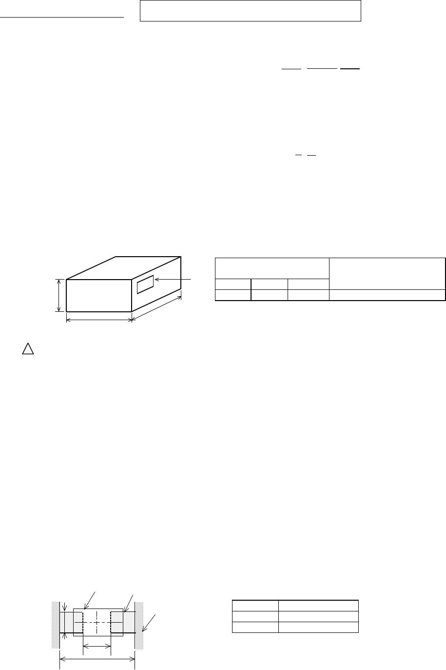
9.8. Specification of Outer Case
Outer Case Dimensions
(mm)
Standard Reel Quantity
in Outer Case (Reel)
W D H
186 186 93 5
Above Outer Case size is typical. It depends on a quantity of an order.
10. Caution
Limitation of Applications
Please contact us before using our products for the applications listed below which require especially
high reliability for the prevention of defects which might directly cause damage to the third party's life,
body or property.
(1) Aircraft equipment (6) Transportation equipment (vehicles, trains, ships, etc.)
(2) Aerospace equipment
(7) Traffic signal equipment
(3) Undersea equipment
(8) Disaster prevention / crime prevention equipment
(4) Power plant control equipment (9) Data-processing equipment
(5) Medical equipment
(10) Applications of similar complexity and /or reliability
requirements to the applications listed in the above
11. Notice
Products can only be soldered with reflow.
This product is designed for solder mounting.
Please consult us in advance for applying other mounting method such as conductive adhesive.
11.1 Land pattern designing
Recommended land patterns for reflow soldering are as follows:
These have been designed for Electric characteristics and solderability.
Please follow the recommended patterns. Otherwise, their performance which includes electrical performance
or solderability may be affected, or result to "position shift" in soldering process.
(in mm)
a 0.50
b 1.2
c 0.65
W
D
Label
H
a
b
c
Chip Coil
Solder resist
Land

LQW15AN4N3B00D

Mfr. #:
Manufacturer:
Murata Electronics
Description:
Fixed Inductors 4.3 NH +-.1NH
Lifecycle:
New from this manufacturer.
Delivery:
DHL FedEx Ups TNT EMS
Payment:
T/T Paypal Visa MoneyGram Western Union