NCP1082
http://onsemi.com
13
Ilim1
Vds_pgood
threshold
VPORTNx
Pass Switch
Inrush
I_pass_switch
NCP1082
RTN
VDS_PGOOD
0
1
VDDA1
VDDA1
1 V / 9.2 V
2 V
Current_limit_ON
&
detector
Figure 13. Inrush and Ilim1 Selection Mechanism
VDDA1
When VPORT reaches the UVLO_on level, the Cpd
capacitor is charged with the INRUSH current (in order to
limit the internal power dissipation of the passswitch).
Once the Cpd capacitor is fully charged, the current limit
switches from the inrush current to the operational current
level (ilim1) as shown in Figure 13. This transition occurs
when both following conditions are satisfied:
1. The VDS of the passswitch is below the
Vds_pgood low level (1 V typical).
2. The passswitch is no longer in current limit
mode, meaning the gate of the passswitch is
“high” (above 2 V typical).
The operational current limit will stay selected as long as
Vds_pgood is true (meaning that RTNVPORTN
1,2
is
below the high level of Vds_pgood). This mechanism allows
a current level transition without any current spike in the
passswitch because the operational current limit (ilim1) is
enabled once the passswitch is not limiting the current
anymore, meaning that the Cpd capacitor is fully charged.
Thermal Shutdown
The NCP1082 includes thermal protection which shuts
down the device in case of high power dissipation. Once the
thermal shutdown (TSD) threshold is exceeded, following
blocks are turned off:
DCDC controller
Passswitch
VDDH and VDDL regulators
CLASS regulator
When the TSD error disappears and if the input line
voltage is still above the UVLO level, the NCP1082
automatically restarts with the current limit set in the inrush
state, the DCDC controller is disabled and the Css
(softstart capacitor) discharged. The DCDC controller
becomes operational as soon as RTNVPORTN
1,2
is below
the Vds_pgood threshold.
NCP1082
http://onsemi.com
14
DCDC Converter Controller
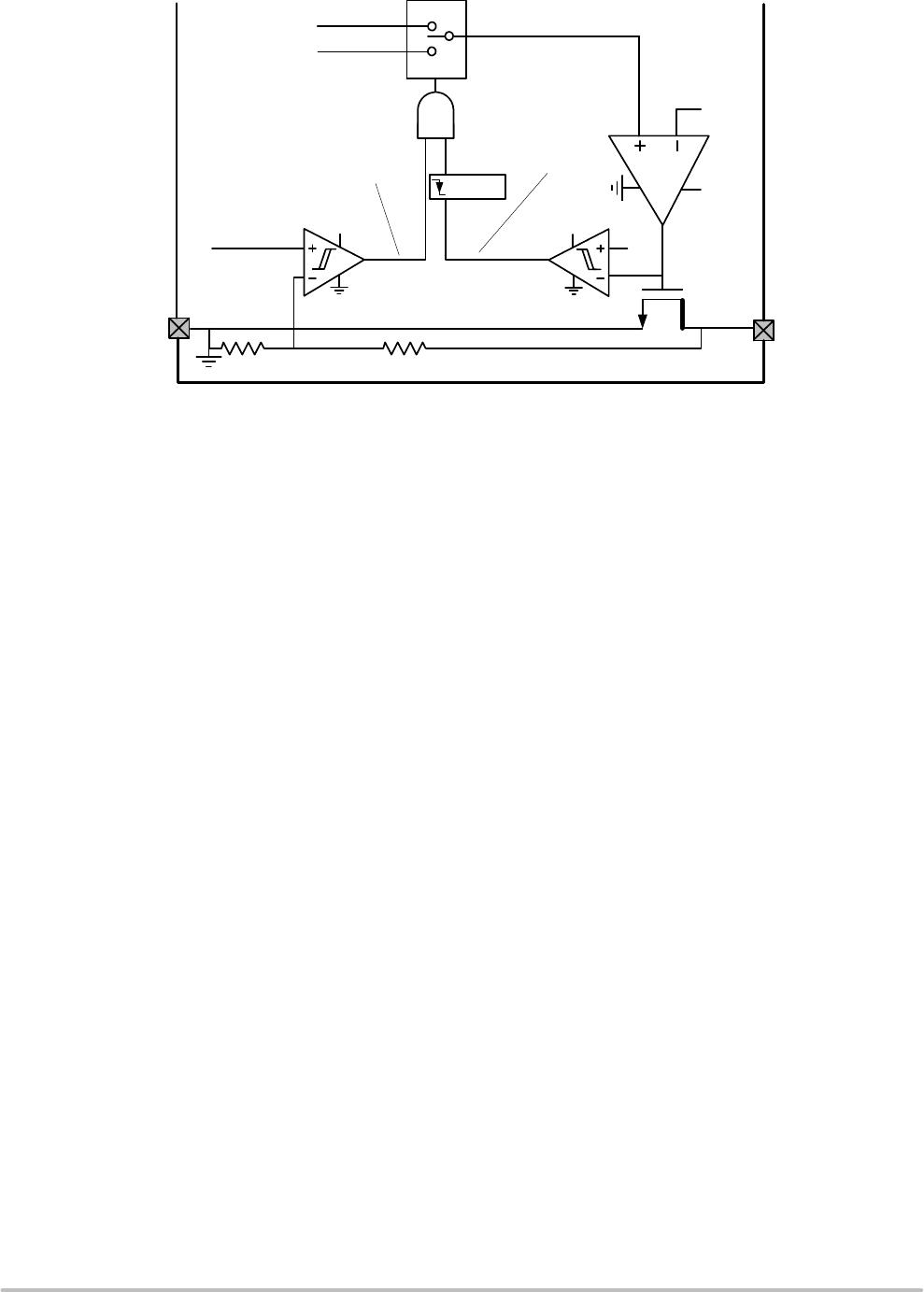
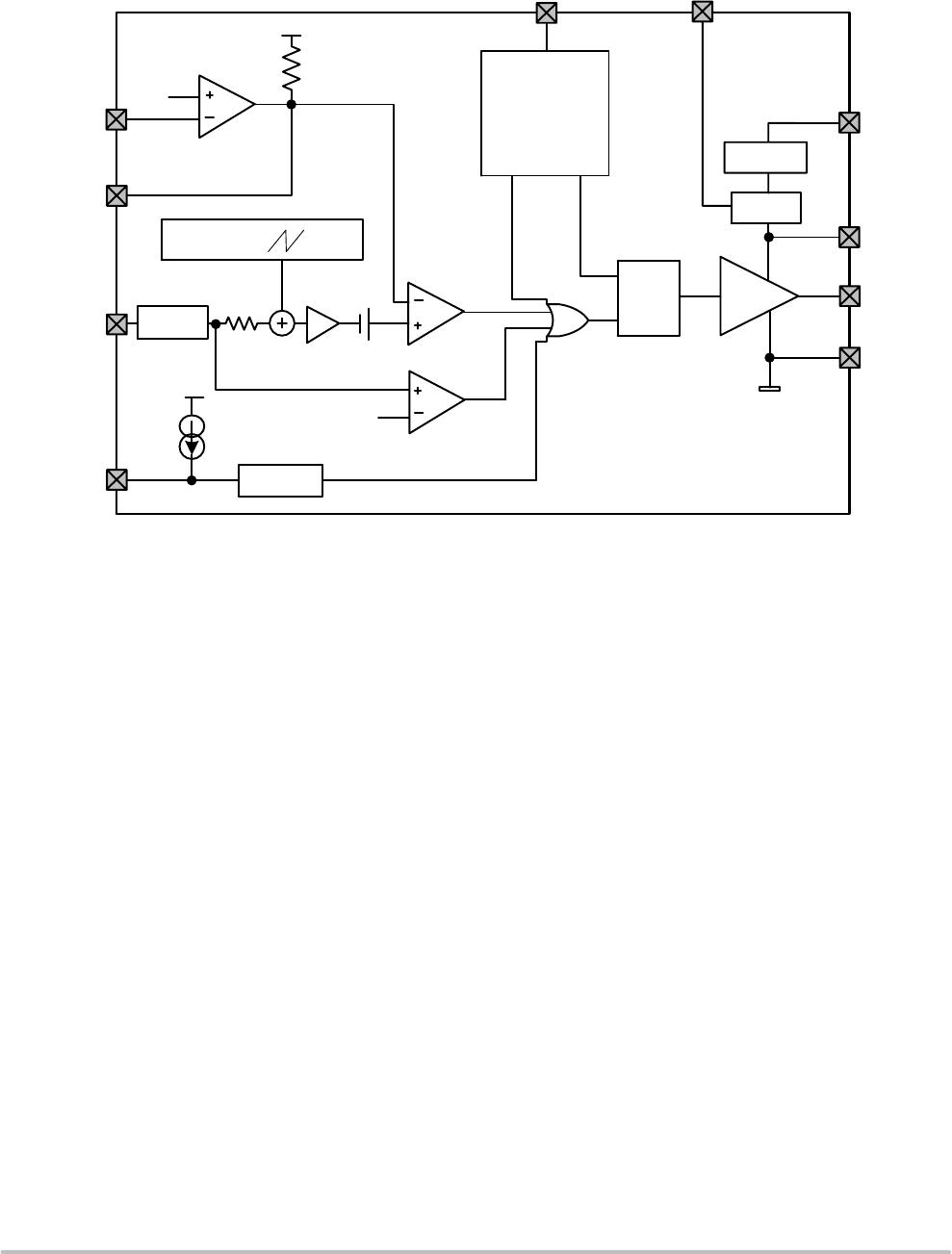
The NCP1082 implements a current mode DCDC converter controller which is illustrated in Figure 14.
VDDL
FB
CS
360 mV
Oscillator
COMP
SS
Gate
Driver
PWM comp
OSC
VDDL
VDDL
Blanking
time
Current Slope
Compensation
2
Softstart
R
S
Q
1.45 V
1.2 V
Current limit
comp
0
9 V LDO
3.3 V LDO
GATE
VDDH
ARTN
VPORTP
Set
CLK
Reset
CLK
Figure 14. DCDC Controller Block Diagram
5 kW
10 mA
11 kW
5 mA
&
Sawtooth
Generator
Internal VDDH and VDDL Regulators and Gate Driver
An internal linear regulator steps down the VPORTP
voltage to a 9 V output on the VDDH pin. VDDH supplies
the internal gate driver circuit which drives the GATE pin
and the gate of the external power MOSFET. The NCP1082
gate driver supports an external MOSFET with high Vth and
high input gate capacitance. A second LDO regulator steps
down the VDDH voltage to a 3.3 V output on VDDL. VDDL
powers the analog circuitry of the DCDC controller.
In order to prevent uncontrolled operations, both regulators
include poweronreset (POR) detectors which prevent the
DCDC controller from operating when either VDDH or
VDDL is too low. In addition, an overvoltage lockout
(OVLO) on the VDDH supply disables the gate driver in case
of an openloop converter with a configuration using the bias
winding of the transformer (see Figure 4).
Both VDDH and VDDL regulators turn on as soon as
VPORT reaches the Vuvlo_on threshold.
Error Amplifier
In nonisolated converter topologies, the high gain
internal error amplifier of the NCP1082 and the internal
1.2 V reference voltage regulate the DCDC output voltage.
In this configuration, the feedback loop compensation
network should be inserted between the FB and COMP pins
as shown in Figures 3, 4 and 5.
In isolated topologies the error amplifier is not used
because it is already implemented externally with the shunt
regulator on the secondary side of the DCDC controller
(see Figure 2). Therefore the FB pin must be strapped to
ARTN and the output transistor of the optocoupler has to
be connected on the COMP pin where an internal 5 kW
pullup resistor is tied to the VDDL supply (see Figure 14).
SoftStart
The softstart function provided by the NCP1082 allows
the output voltage to ramp up in a controlled fashion,
eliminating output voltage overshoot. This function is
programmed by connecting a capacitor C
SS
between the SS
and ARTN pins.
While the DCDC controller is in POR, the capacitor C
SS
is fully discharged. After coming out of POR, an internal
current source of 5 mA typically starts charging the capacitor
C
SS
to initiate softstart. When the voltage on SS pin has
reached 0.45 V (typical), the gate driver is enabled and
DCDC operation starts with a duty cycle limit which
increases with the SS pin voltage. The softstart function is
finished when the SS pin voltage goes above 1.6 V for which
the duty cycle limit reaches its maximum value of 80
percent.
Softstart can be programmed by using the following
equation:
t
SS
(ms) + 0.23 C
SS
(nF)
NCP1082
http://onsemi.com
15
Current Limit Comparator
The NCP1082 current limit block behind the CS pin
senses the current flowing in the external MOSFET for
current mode control and cyclebycycle current limit. This
is performed by the current limit comparator which, on the
CS pin, senses the voltage across the external Rcs resistor
located between the source of the MOSFET and the ARTN
pin.
The NCP1082 also provides a blanking time function on
CS pin which ensures that the current limit and PWM
comparators are not prematurely trigged by the current spike
that occurs when the switching MOSFET turns on.
Slope Compensation Circuitry
To overcome subharmonic oscillations and instability
problems that exist with converters running in continuous
conduction mode (CCM) and when the duty cycle is close
or above 50 percent, the NCP1082 integrates a current slope
compensation circuit. The amplitude of the added slope
compensation is typically 110 mV over one cycle.
As an example, for an operating switching frequency of
250 kHz, the internal slope provided by the NCP1082 is
27.5 mV/ mA typically.
DCDC Controller Oscillator
The frequency is configured with the Rosc resistor
inserted between OSC and ARTN, and is defined by the
following equation:
R
OSC
(kW) +
38600
F
OSC
(kHz)
The duty cycle limit is fixed internally at 80 percent.

NCP1082DER2G

Mfr. #:
Manufacturer:
ON Semiconductor
Description:
Switching Controllers POE-PD 13W DC-DC AUX SUPP
Lifecycle:
New from this manufacturer.
Delivery:
DHL FedEx Ups TNT EMS
Payment:
T/T Paypal Visa MoneyGram Western Union

Products related to this Datasheet