EVAL-ADP1710/ADP1711
Rev. 0 | Page 7 of 8
GROUND CURRENT MEASUREMENTS
GND
GND GND
GND
C1 C2
U1
C3
R1
R2
VIN VOUT
EN
J1
EVAL-ADP1710/ADP1711
NC/ADJ/BYP
+
_
VOLTAGE
SOURCE
AMMETER
LOAD
_
+
μA
NC = NO CONNECT
6311-010
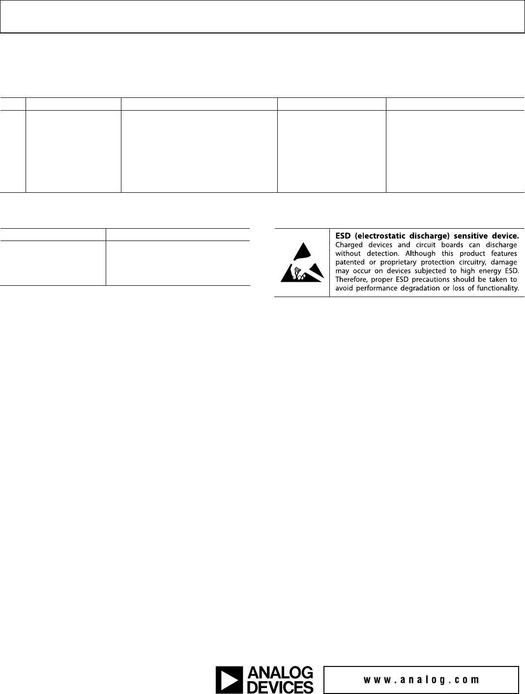
Figure 9.
Figure 9 shows how the evaluation board can be connected
to a voltage source and a current meter for ground current
measurements. A resistor can be used as the load for the
regulator. Ensure the resistor has a power rating adequate to
handle the power expected to be dissipated across it. An electronic
load can be used as an alternative. Ensure the voltage source
used can supply adequate current for the expected load levels.
Follow these steps to connect to a voltage source and current meter:
1. Connect the positive terminal (+) of the voltage source to
the VIN pad on the evaluation board.
2. Connect the positive terminal (+) of the current meter to
one of the GND pads of the evaluation board.
3. Connect the negative terminal (−) of the current meter to
the negative (−) terminal of the voltage source.
4. Connect a load between the VOUT pad of the evaluation
board and the negative (−) terminal of the voltage source.
5. The voltage source can now be turned on. If J1 is inserted
(this connects EN to VIN for automatic startup), then the
regulator powers up.
GROUND CURRENT CONSUMPTION
Ground current measurements are a way of determining how
much current the regulator’s internal circuits are consuming,
while performing the regulation function. To be efficient, the
regulator must consume as little current as possible. Typically,
the regulator consumes maximum current when supplying its
largest load level (150 mA). Figure 10 shows the typical ground
current consumption for various load levels.
1100
0
0.1
I
LOAD
(mA)
I
GND
(µA)
1000
900
800
700
600
500
400
300
200
100
1000
110100
06311-011
Figure 10. Ground Current vs. Load Current.
When the device is disabled (EN = 0 V), ground current is
reduced to less than 1 μA.
Note: Larger ground current levels are observed when using an
evaluation board with R1 and R2 present.