FEDR44V100A-01
MR44V100A
12/18
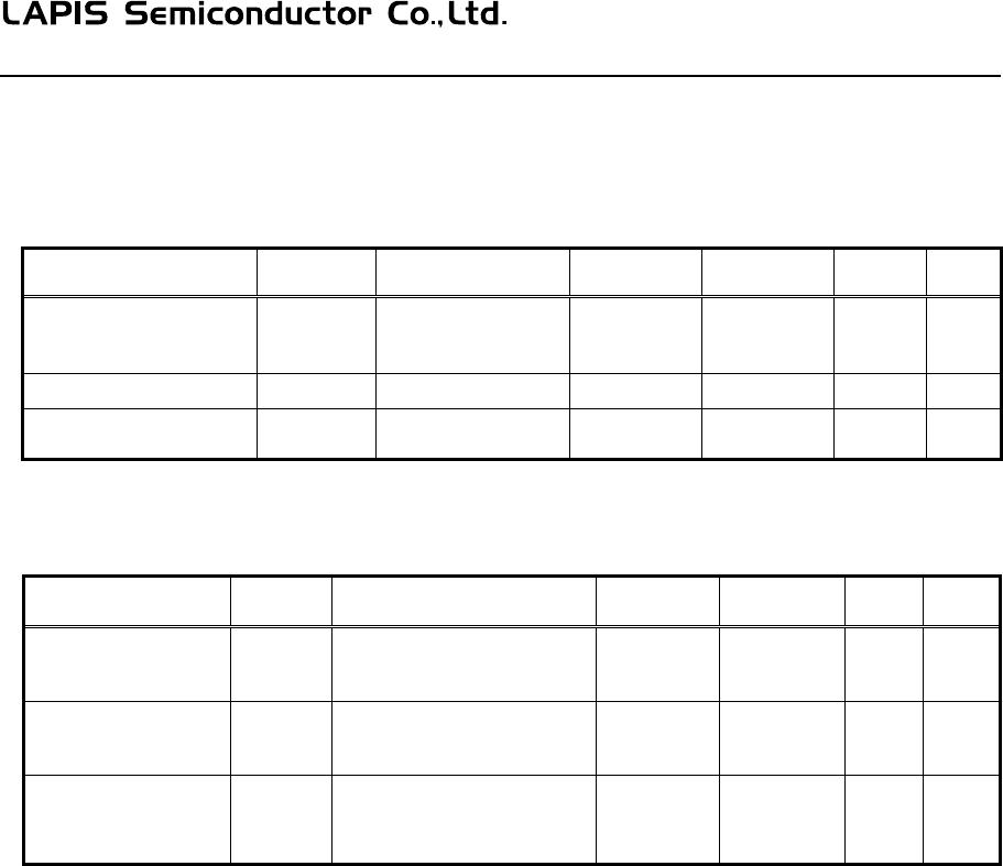
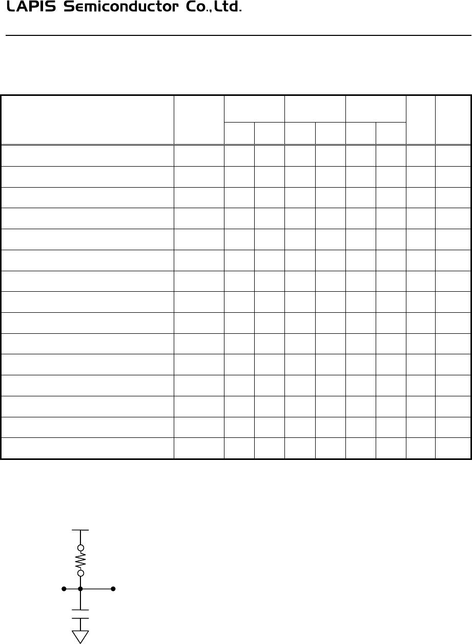
AC CHARACTERISTICS
V
CC
=Max. to Min., Ta=Topr.
Parameter Symbol
F/S-mode
F/S-mode
Plus
HS-mode
Unit Note
Min. Max. Min. Max. Min. Max.
Clock frequency
f
SCL
D.C. 400 D.C. 1000 DC 3400 KHz
Clock Low time tLOW 1300 — 500 — 160 — ns
Clock High time tHIGH 600 — 300 — 60 — ns
Output Data delay time tAA — 900 — 450 — 130 ns
BUS release time before transfer start tBUF 1300 — 500 — 300 — ns
Start condition hold time tHD:STA 600 — 250 — 160 — ns
Start condition setup time tSU:STA 600 — 250 — 160 — ns
Input data hold time tHD:DAT 0 — 0 — 0 — ns
Input data setup time tSU:DAT 100 — 100 — 10 — ns
SDA, SCL rise time tR — 300 — 300 — 80 ns 1
SDA, SCL fall time tF — 300 — 120 — 80 ns 1
Stop condition setup time tSU:STO 600 — 250 — 160 — ns
Output data hold time tDH 0 — 0 — 0 — ns
Noise removal time (SDA, SCL) tSP — 50 — 50 — 5 ns
Sleep mode recovery time tREC — 100 — 100 — 100 µs
Note: 1. Not 100% tested
Equivalent AC Load Circuit
3.3V
1kΩ
Out
ut
100pF