www.vishay.com
2
Document Number: 70818
S11-0975-Rev. D, 16-May-11
Vishay Siliconix
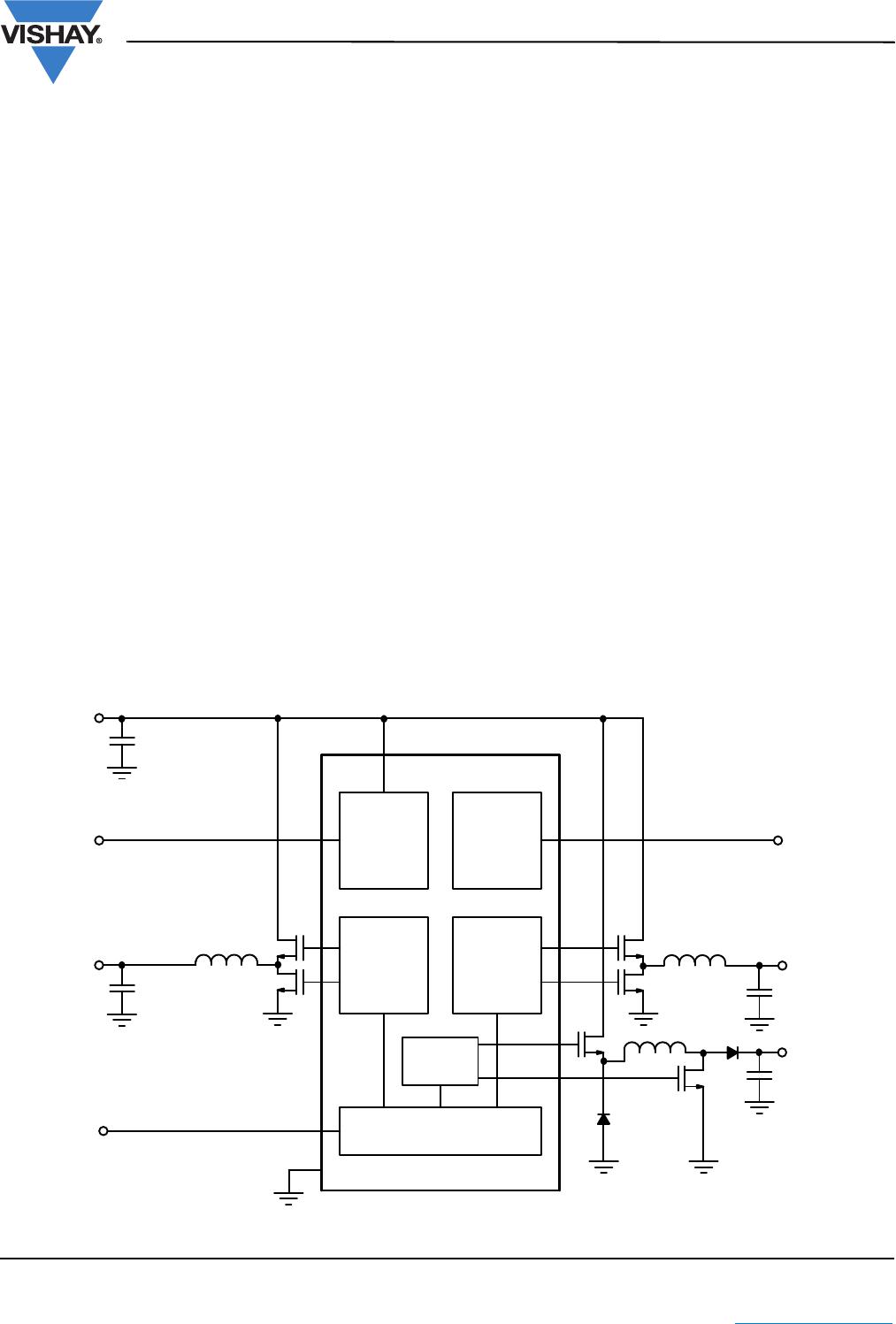
Si9136
This document is subject to change without notice.
THE PRODUCTS DESCRIBED HEREIN AND THIS DOCUMENT ARE SUBJECT TO SPECIFIC DISCLAIMERS, SET FORTH AT www.vishay.com/doc?91000
Notes:
a. Device Mounted with all leads soldered or welded to PC board.
b. Derate 9.25 mW/°C above 90 °C.
Stresses beyond those listed under “Absolute Maximum Ratings” may cause permanent damage to the device. These are stress ratings only, and functional operation
of the device at these or any other conditions beyond those indicated in the operational sections of the specifications is not implied. Exposure to absolute maximum
rating conditions for extended periods may affect device reliability.
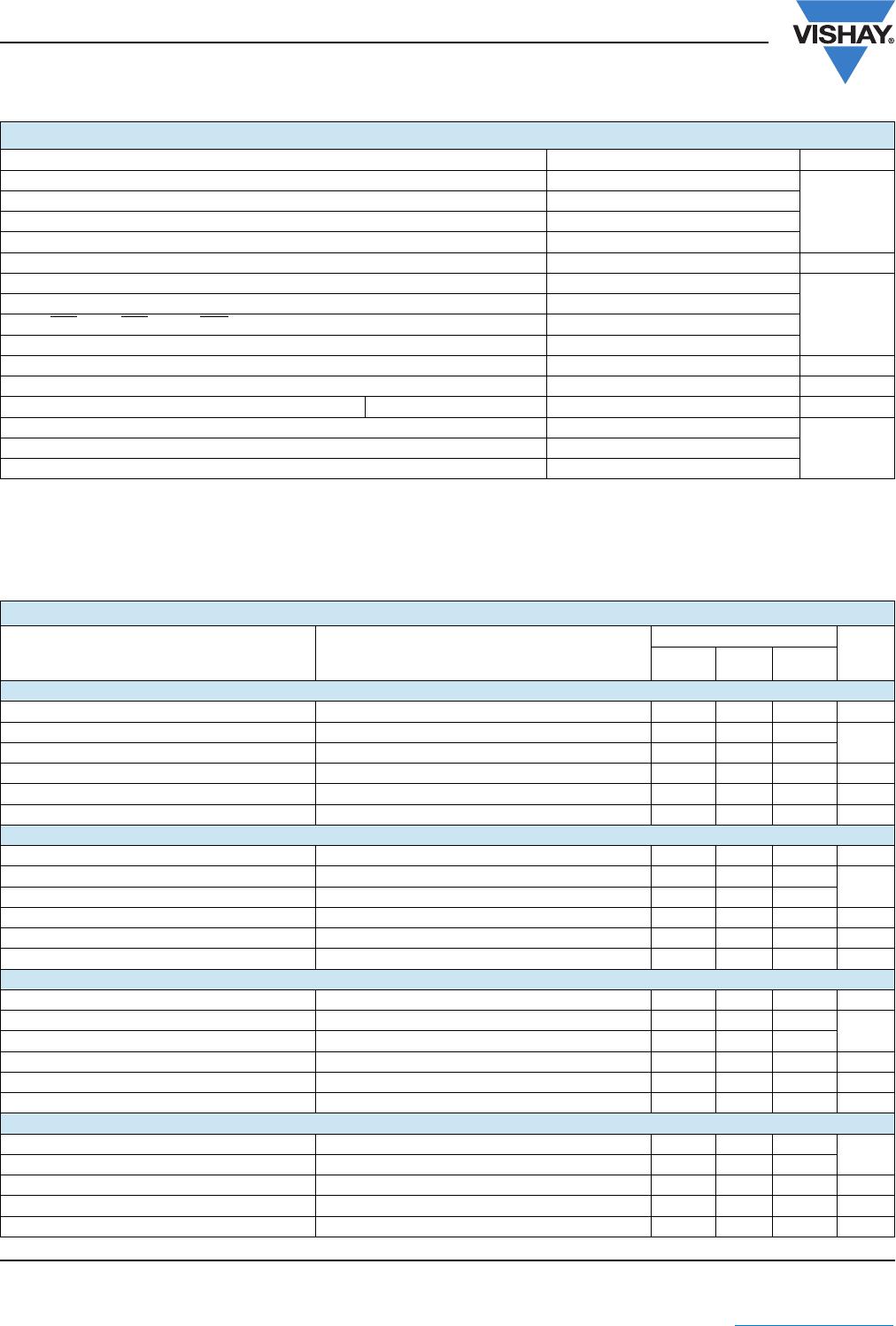
ABSOLUTE MAXIMUM RATINGS
Parameter Limit Unit
V
IN
to GND - 0.3 to + 36 V
V
P
GND
to GND ± 2
V
L
to GND - 0.3 to + 6.5 V
BST
3
, BST
5
, BSTFY to GND - 0.3 V to + 36 V
V
L
Short to GND Continuous
LX
3
to BST
3
; LX
5
to BST
5
; LXFY to BST - 6.5 V to 0.3 V
V
Inputs/Outputs to GND (CS
3
, CS
5
, CSP, CSN) - 0.3 V to (V
L
+ 0.3 V)
5 ON/OFF
, 3 ON/OFF, 12 ON/OFF - 0.3 V to + 5.5 V
DL3, DL5 to PGND - 0.3 V to (V
L
+ 0.3 V)
DLFY to PGND Input of Flyback
DH3 to LX
3
, DH5 to LX
5
, DHFY to LXFY - 0.3 V to (BSTX + 0.3 V) V
Continuous Power Dissipation (T
A
= 90 °C)
a
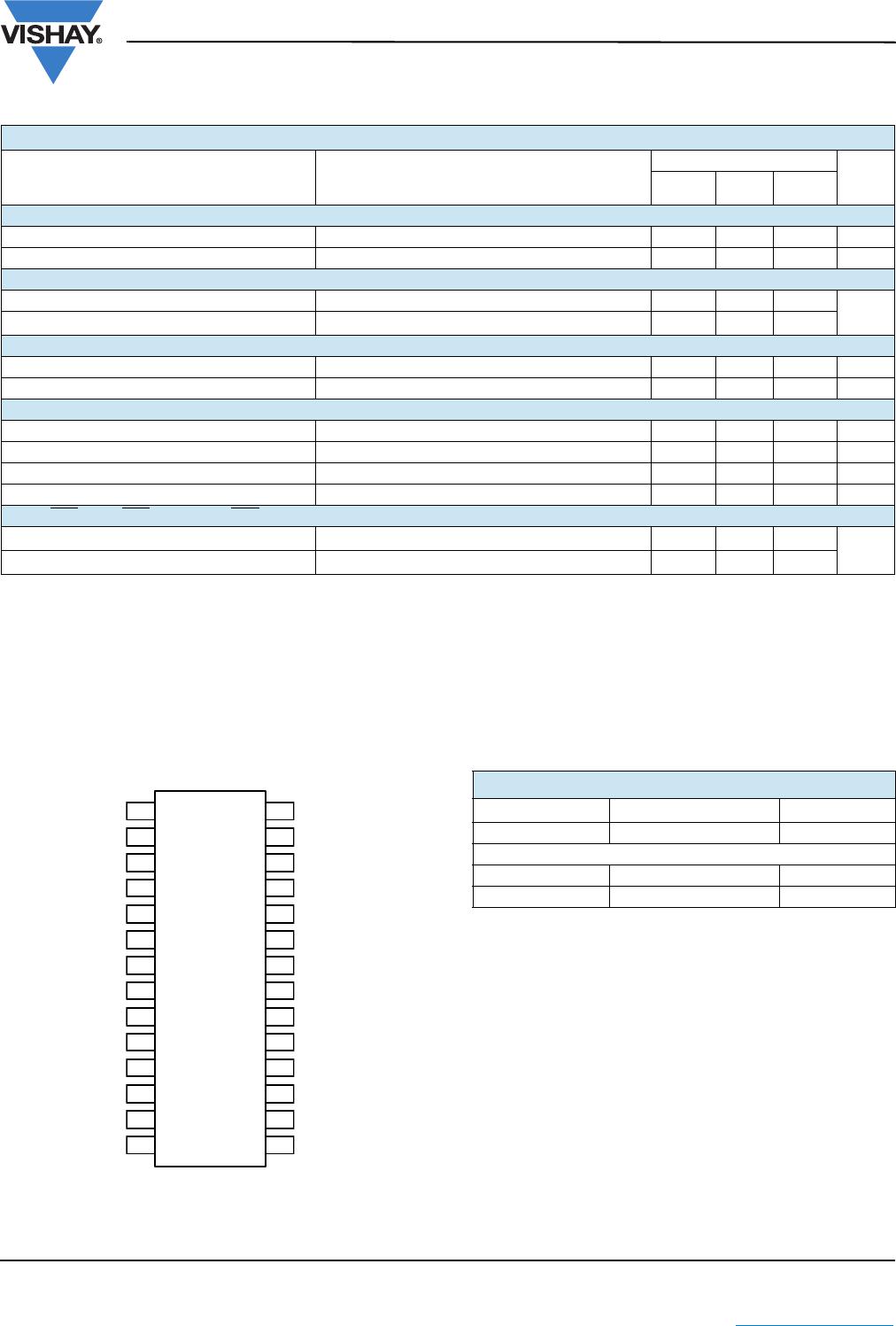
28-Pin SSOP
b
572 mW
Operating Temperature Range 0 °C to 90 °C
°C
Storage Temperature Range - 40 °C to 125 °C
Lead Temperature (Soldering, 10 Sec.) 300
SPECIFICATIONS
Parameter
Specific Test Conditions
V
IN
= 15 V , I
VL
= I
REF
= 0 mA
T
A
= 0 °C to 90 °C, All Converters ON
Limits
Unit
Min.
a
Typ.
b
Max.
a
3.3 V Buck Controller
Total Regulation (Line, Load, and Temperature) V
IN
= 6 to 30 V, 0 < V
CS3
- V
FB3
< 90 mV 3.23 3.33 3.43 V
Line Regulation V
IN
= 6 to 30 V ± 0.5
%
Load Regulation 0 < V
CS3
- V
FB3
< 90 mV ± 0.5
Current Limit V
CS3
- V
FB3
90 125 160 mV
Bandwidth L = 10 µH, C = 330 µF 50 kHz
Phase Margin R
SENSE
= 20 m 65 °
5 V Buck Controller
Total Regulation (Line, Load, and Temperature) V
IN
= 6 to 30 V, 0 < V
CS5
- V
FB5
< 90 mV 4.88 5.03 5.18 V
Line Regulation V
IN
= 6 to 30 V ± 0.5
%
Load Regulation 0 < V
CS5
- V
FB5
< 90 mV ± 0.5
Current Limit V
CS5
- V
FB5
90 125 160 mV
Bandwidth L = 10 µH, C = 330 µF 50 kHz
Phase Margin R
SENSE
= 20 m 65 °
12 V Flyback Controller
Total Regulation (Line, Load, and Temperature) V
IN
= 6 to 30 V, 0 < V
CSP
- V
CSN
< 300 mV 11.4 12.0 12.6 V
Line Regulation V
IN
= 6 to 30 V ± 0.5
%
Load Regulation 0 < V
CSP
- V
FBN
< 300 mV ± 0.5
Current Limit V
CSP
- V
CSN
330 410 500 mV
Bandwidth L = 10 µH, C = 100 µF 10 kHz
Phase Margin R
SENSE
= 100 m, C
comp
= 120 pF 65 °
Internal Regulator
V
L
Output All Converters OFF, V
IN
> 5.5, 0 < I
L
< 30 mA 4.7 5.5
V
V
L
Fault Lockout Voltage 3.6 4.2
V
L
Fault Lockout Hysteresis 75 mV
V
L
/FB5 Switchover Voltage 4.2 4.7 V
V
L
/FB5 Switchover Hysteresis 75 mV