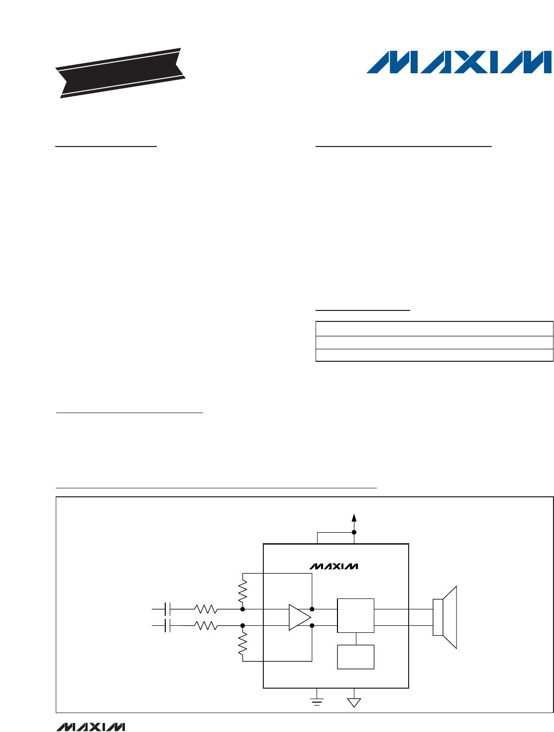
MAX9730
2.4W, Single-Supply, Class G Power Amplifier
2 _______________________________________________________________________________________
ABSOLUTE MAXIMUM RATINGS
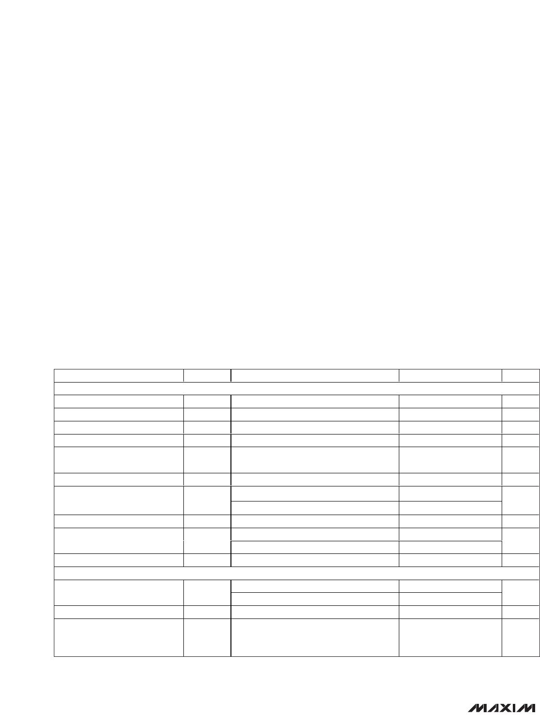
ELECTRICAL CHARACTERISTICS
(V
CC
= V
CPVDD
= V
SHDN
= 3.6V, V
GND
= V
CPGND
= 0V, R
IN+
= R
IN-
= 10kΩ, R
FB+
= R
FB-
= 10kΩ, R
FS
= 100kΩ, C1 = 4.7µF, C2 =
10µF; speaker load resistors (R
L
) are terminated between OUT+ and OUT-, unless otherwise stated; T
A
= T
MIN
to T
MAX
, unless other-
wise noted. Typical values are at T
A
= +25°C.) (Notes 1, 2)
Stresses beyond those listed under “Absolute Maximum Ratings” may cause permanent damage to the device. These are stress ratings only, and functional
operation of the device at these or any other conditions beyond those indicated in the operational sections of the specifications is not implied. Exposure to
absolute maximum rating conditions for extended periods may affect device reliability.
(Voltages with respect to GND.)
V
CC
, CPV
DD
.............................................................-0.3V to +6V
PV
SS
, SV
SS
...............................................................-6V to +0.3V
CPGND..................................................................-0.3V to +0.3V
OUT+, OUT-...................................(SV
SS
- 0.3V) to (V
CC
+ 0.3V)
IN+, IN-, FB+, FB- ......................................-0.3V to (V
CC
+ 0.3V)
C1N..........................................(PV
SS
- 0.3V) to (CPGND + 0.3V)
C1P.......................................(CPGND - 0.3V) to (CPV
DD
+ 0.3V)
FS, SHDN ...................................................-0.3V to (V
CC
+ 0.3V)
Continuous Current Into/Out of
OUT+, OUT-, V
CC
, GND, SV
SS
.....................................800mA
CPV
DD
, CPGND, C1P, C1N, PV
SS
.................................800mA
Any Other Pin ..................................................................20mA
Continuous Power Dissipation (T
A
= +70°C)
20-Bump WLP (derate 10.3mW/°C above +70°C)........827mW
28-Pin TQFN (derate 20.8mW/°C above +70°C) ........1667mW
Operating Temperature Range ...........................-40°C to +85°C
Storage Temperature Range .............................-65°C to +150°C
Lead Temperature (soldering, 10s) ................................+300°C
Bump Temperature (soldering) Reflow............................+260°C