MAX9730
2.4W, Single-Supply, Class G Power Amplifier
6 _______________________________________________________________________________________6 _______________________________________________________________________________________
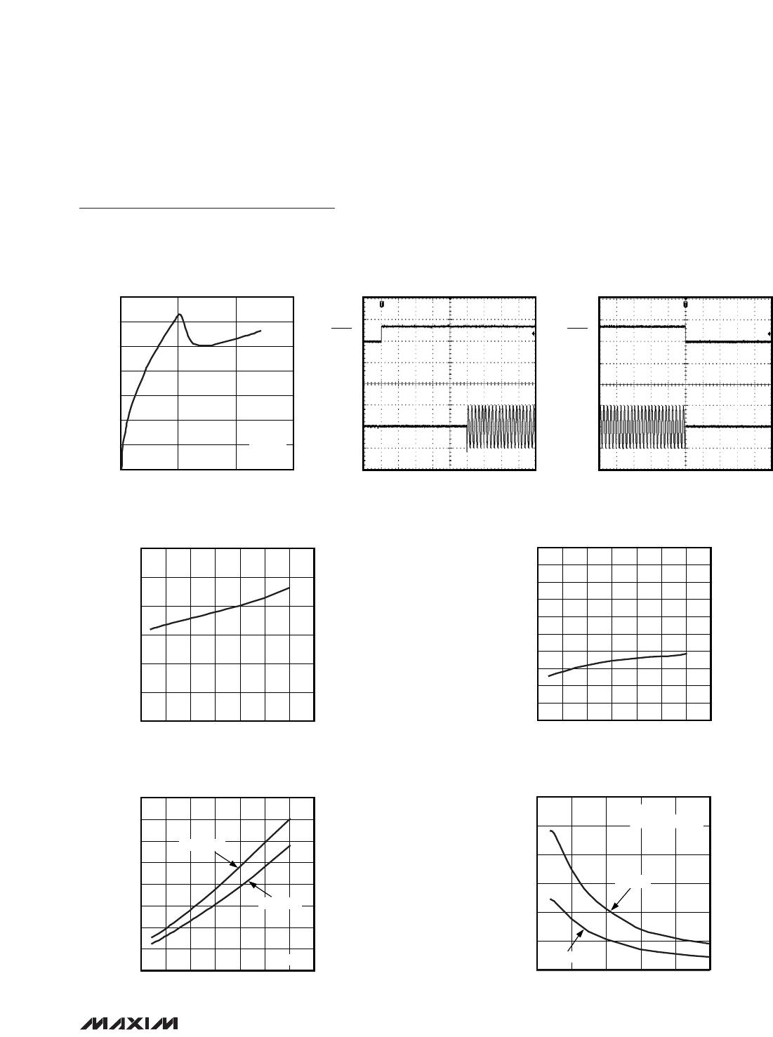
CLASS G OUTPUT WAVEFORM
MAX9730 toc17
200μs/div
OUT+ - OUT-
10V/div
OUT-
5V/div
OUT+
5V/div
1% THD+N
FREQUENCY RESPONSE
MAX9730 toc18
FREQUENCY (Hz)
GAIN (dB)
10k1k100
2
4
6
8
10
12
14
16
18
20
0
10 100k
P
OUT
= 1W
PACKAGE THERMAL DISSIPATION AND
OUTPUT POWER vs. TEMPERATURE
MAX9730 toc19
TEMPERATURE (°C)
PACKAGE THERMAL DISSIPATION (W)
OUTPUT POWER (W)
80706050403020100-10-20-30
0.5
1.0
1.5
2.0
2.5
3.0
3.5
0
0.5
1.0
1.5
2.0
2.5
3.0
3.5
0
-40 90
V
CC
= 5V
OUTPUT POWER
PACKAGE THERMAL
DISSIPATION
Pin Description
Typical Operating Characteristics (continued)
(V
CC
= V
CPVDD
= V
SHDN
= 3.6V, V
GND
= V
CPGND
= 0V, R
IN+
= R
IN-
= 10kΩ, R
FB+
= R
FB-
= 10kΩ, R
FS
= 100kΩ, C1 = 4.7µF, C2 =
10µF, R
L
= 8Ω; speaker load resistors (R
L
) are terminated between OUT+ and OUT-, unless otherwise stated; T
A
= T
MIN
to T
MAX
,
unless otherwise noted. Typical values are at T
A
= +25°C.) (Notes 1, 2)
PIN
TQFN WLP
NAME FUNCTION
1B2SHDN Shutdown
2, 5, 6, 8, 11, 17,
19, 23, 25, 28
— N.C. No Connection. No internal connection.
3 A2 C1P
Charge-Pump Flying Capacitor, Positive Terminal. Connect a 4.7µF
capacitor between C1P and C1N.
4A3CPV
DD
Charge-Pump Positive Supply
7 A4 FB- Negative Amplifier Feedback
9 A5 IN- Negative Amplifier Input
10 B5 IN+ Positive Amplifier Input
12 B4 FB+ Positive Amplifier Feedback
13 C5 FS
Charge-Pump Frequency Set. Connect a 100kΩ resistor from FS to
GND to set the charge-pump switching frequency.
14, 22 D1, D5 V
CC
Supply Voltage. Bypass with a 10µF capacitor to GND.
15, 21 C2, C4 SV
SS
Amplifier Negative Power Supply. Connect to PV
SS
.
16 D4 OUT- Negative Amplifier Output
18 D3 GND Ground
20 D2 OUT+ Positive Amplifier Output
24 C1 PV
SS
Charge-Pump Output. Connect a 10µF capacitor between PV
SS
and
CPGND.
26 B1 C1N
Charge-Pump Flying Capacitor, Negative Terminal. Connect a 4.7µF
capacitor between C1N and C1P.
27 A1 CPGND Charge-Pump Ground. Connect to GND.
EP — EP Exposed Pad. Connect the TQFN EP to GND.