VS-ST303SP Series
www.vishay.com
Vishay Semiconductors
Revision: 15-Mar-17
3
Document Number: 94375
For technical questions within your region: DiodesAmericas@vishay.com
, DiodesAsia@vishay.com, DiodesEurope@vishay.com
THIS DOCUMENT IS SUBJECT TO CHANGE WITHOUT NOTICE. THE PRODUCTS DESCRIBED HEREIN AND THIS DOCUMENT
ARE SUBJECT TO SPECIFIC DISCLAIMERS, SET FORTH AT www.vishay.com/doc?91000
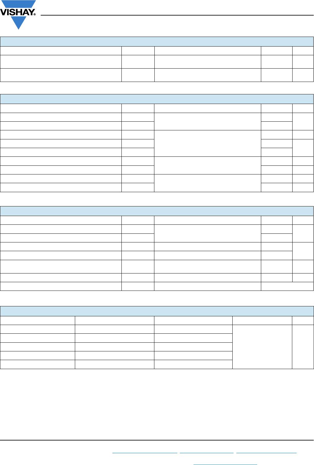
Note
• The table above shows the increment of thermal resistance R
thJ-hs
when devices operate at different conduction angles than DC
BLOCKING
PARAMETER SYMBOL TEST CONDITIONS VALUES UNITS
Maximum critical rate of rise of off-state voltage dV/dt
T
J
= T
J
maximum, linear to 80 % V
DRM
,
higher value available on request
500 V/μs
Maximum peak reverse and off-state leakage
current
I
RRM
,
I
DRM
T
J
= T
J
maximum, rated V
DRM
/V
RRM
applied 50 mA
TRIGGERING
PARAMETER SYMBOL TEST CONDITIONS VALUES UNITS
Maximum peak gate power P
GM
T
J
= T
J
maximum, f = 50 Hz, d% = 50
60
W
Maximum average gate power P
G(AV)
10
Maximum peak positive gate current I
GM
T
J
= T
J
maximum, t
p
5 ms
10 A
Maximum peak positive gate voltage +V
GM
20
V
Maximum peak negative gate voltage -V
GM
5
Maximum DC gate currrent required to trigger I
GT
T
J
= 25 °C, V
A
= 12 V, R
a
= 6
200 mA
Maximum DC gate voltage required to trigger V
GT
3V
Maximum DC gate current not to trigger I
GD
T
J
= T
J
maximum, rated V
DRM
applied
20 mA
Maximum DC gate voltage not to trigger V
GD
0.25 V
THERMAL AND MECHANICAL SPECIFICATIONS
PARAMETER SYMBOL TEST CONDITIONS VALUES UNITS
Maximum operating junction temperature range T
J
-40 to +125
°C
Maximum storage temperature range T
Stg
-40 to +150
Maximum thermal resistance, junction to case R
thJC
DC operation 0.10
K/W
Maximum thermal resistance, case to heatsink R
thCS
Mounting surface, smooth, flat and greased 0.03
Mounting force, ± 10 % Non-lubricated threads
48.5
(425)
N · m
(lbf · in)
Approximate weight 535 g
Case style See dimensions - link at the end of datasheet TO-209AE (TO-118)
R
thJ-hs
CONDUCTION
CONDUCTION ANGLE SINUSOIDAL CONDUCTION RECTANGULAR CONDUCTION TEST CONDITIONS UNITS
180° 0.011 0.008
T
J
= T
J
maximum K/W
120° 0.013 0.014
90° 0.017 0.018
60° 0.025 0.026
30° 0.041 0.042

