DG9408E, DG9409E
www.vishay.com
Vishay Siliconix
S16-1452-Rev. A, 25-Jul-16
6
Document Number: 75375
For technical questions, contact: analogswitchtechsupport@vishay.com
THIS DOCUMENT IS SUBJECT TO CHANGE WITHOUT NOTICE. THE PRODUCTS DESCRIBED HEREIN AND THIS DOCUMENT
ARE SUBJECT TO SPECIFIC DISCLAIMERS, SET FORTH AT www.vishay.com/doc?91000
Notes
a. Leakage parameters are guaranteed by worst case test condition and not subject to production test.
b. Room = 25 °C, full = as determined by the operating temperature suffix.
c. The algebraic convention whereby the most negative value is a minimum and the most positive a maximum, is used in this data sheet.
d. Typical values are for DESIGN AID ONLY, not guaranteed nor subject to production testing.
e. Guaranteed by design, not subject to production test.
f. V
IN
= input voltage to perform proper function.
g. R
DON
= R
DON
max. - R
DON
min.
h. Worst case isolation occurs on channel 4 due to proximity to the drain pin.
i. R
DON
flatness is measured as the difference between the minimum and maximum measured values across a defined analog signal.
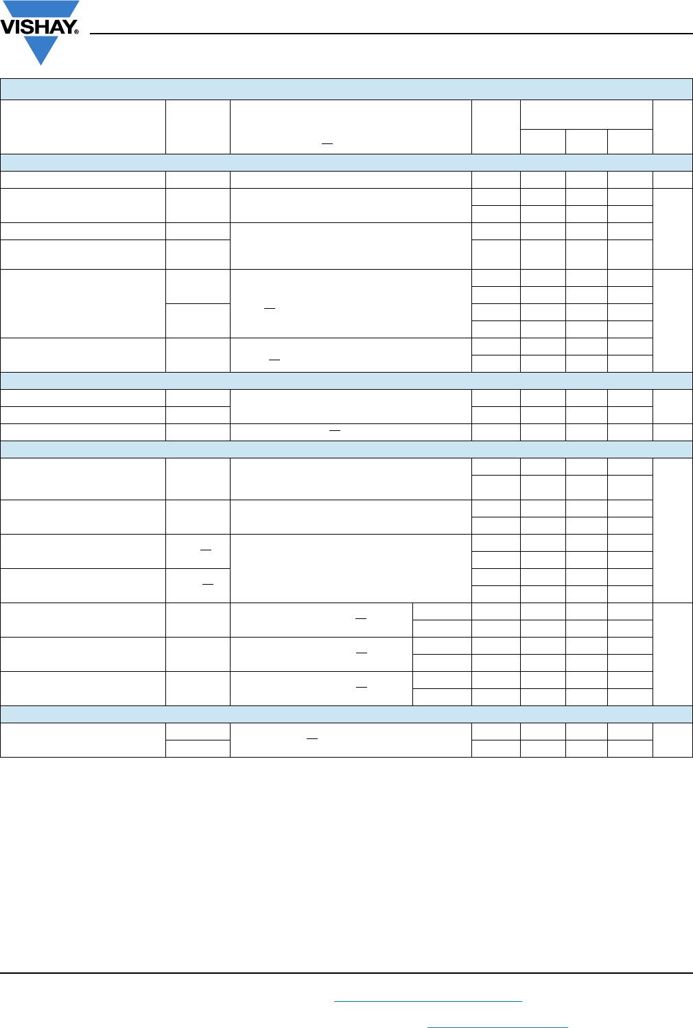
SPECIFICATIONS (Single Supply 3 V)
PARAMETER SYMBOL
TEST CONDITIONS
UNLESS OTHERWISE SPECIFIED
V+ = 3 V, ± 10 %, V- = 0 V
V
EN
= 0.4 V or 1.8 V
f
TEMP.
b
LIMITS
-40 °C to +85 °C
UNIT
MIN.
c
TYP.
d
MAX.
c
Analog Switch
Analog signal range
e
V
ANALOG
Full 0 - 3 V
On-resistance R
ON
V+ = 2.7 V, V
D
= 0.5 V or 2.2 V, I
S
= 5 mA
Room - 13 25.5
Full - - 26.5
R
ON
match between channels
g
R
ON
V+ = 2.7 V, V
D
= 0.5 V or 2.2 V, I
S
= 5 mA
Room - - 3.6
On-resistance flatness
i
R
ON
Flatness
Room - - 13
Switch off leakage current
a
I
S(off)
V+ = 3.3 V
V
S
= 2 V or 1 V, V
D
= 1 or 2 V
Room -2 - 2
nA
Full -15 - 15
I
D(off)
Room -2 - 2
Full -15 - 15
Channel on leakage current
a
I
D(on)
V+ = 3.3 V
V
D
= V
S
= 1 V or 2 V, sequence each switch on
Room -2 - 2
Full -15 - 15
Digital Control
Logic high input voltage V
INH
Full 1.8 - -
V
Logic low input voltage V
INL
Full - - 0.4
Input current
a
I
IN
V
AX
= V
EN
= 1.8 V or 0.4 V Full -1 - 1 μA
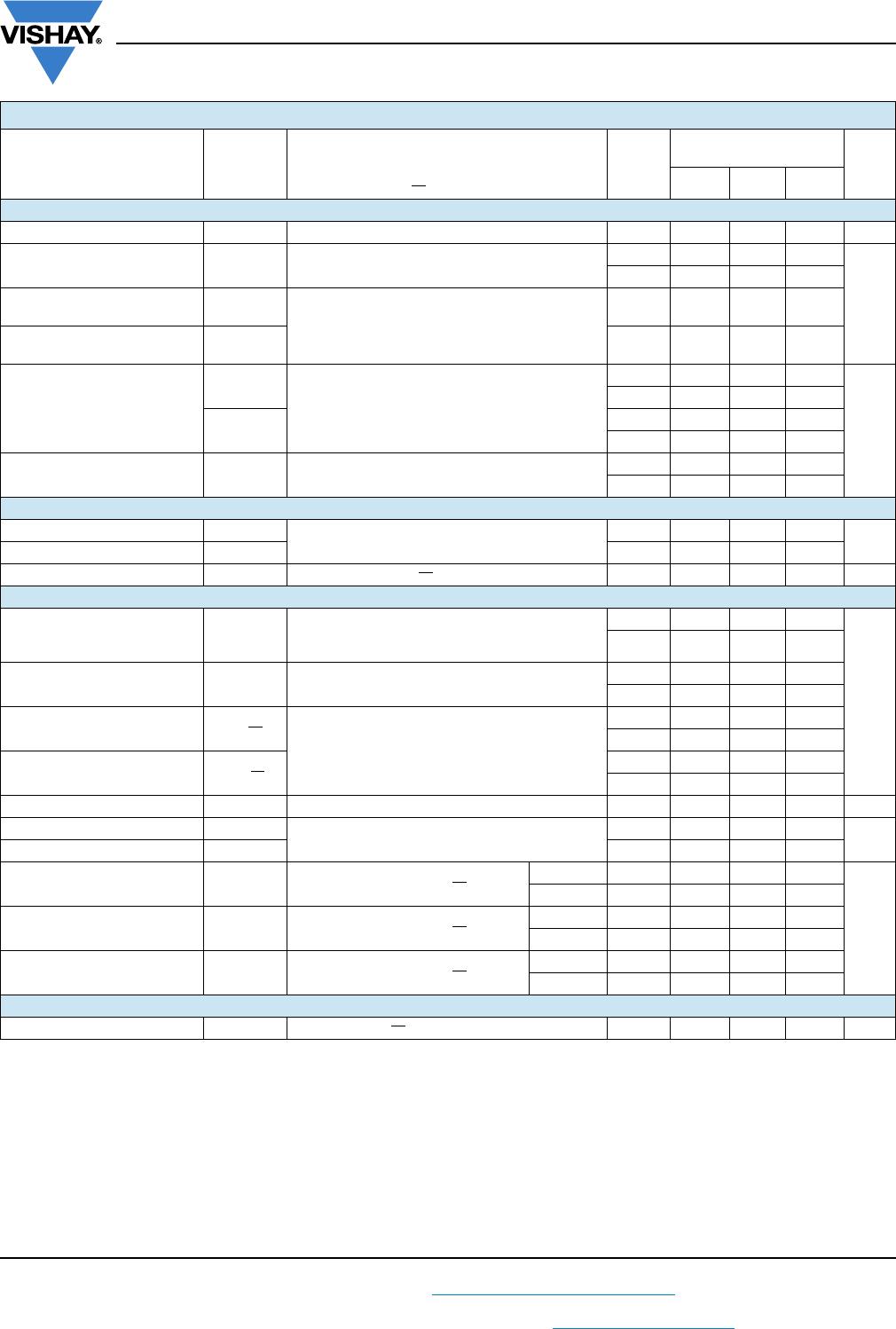
Dynamic Characteristics
Transition time t
TRANS
V
S1
= 1.5 V, V
S8
= 0 V, (DG9408E)
V
S1b
= 1.5 V, V
S4b
= 0 V, (DG9409E)
see fig. 2
Room - 169 245
ns
Full - - 278
Break-before-make time t
BBM
V
S(all)
= V
DA
= 1.5 V
see fig. 4
Room 2 96 -
Full - - -
Enable turn-on time t
ON(EN)
V
AX
= 0 V, V
S1
= 1.5 V (DG9408E)
V
AX
= 0 V, V
S1b
=1.5 V (DG9409E)
see fig. 3
Room - 202 255
Full - - 272
Enable turn-off time t
OFF(EN)
Room - 72 97
Full - - 104
Charge injection
e
QC
L
= 1 nF, R
GEN
= 0, V
GEN
= 0 V Room - 2.1 - pC
Off isolation
e, h
OIRR
f = 100 kHz, R
L
= 1 k
Room - -83 -
dB
Crosstalk
e
X
TALK
Room - -90 -
Source off capacitance
e
C
S(off)
f = 1 MHz, V
S
= 0 V, V
EN
= 1.8 V
DG9408E Room - 20 -
pF
DG9409E Room - 19 -
Drain off capacitance
e
C
D(off)
f = 1 MHz, V
D
= 0 V, V
EN
= 1.8 V
DG9408E Room - 159 -
DG9409E Room - 79 -
Drain on capacitance
e
C
D(on)
f = 1 MHz, V
D
= 0 V, V
EN
= 0 V
DG9408E Room - 179 -
DG9409E Room - 98 -
Power Supplies
Power supply current I+ V
EN
= V
A
= 0 V or V+ Room - - 1 μA