5
FN6305.6
March 3, 2011
Functional Pin Description (SOIC, DFN)
VCC (SOIC Pin 5, DFN Pin 6)
This pin provides the bias supply for the ISL6545x, as well
as the lower MOSFET’s gate, and the BOOT voltage for the
upper MOSFET’s gate. An internal 5V regulator will supply
bias if V
CC
rises above 6.5V (but the LGATE/OCSET and
BOOT will still be sourced by VCC). Connect a well-
decoupled 5V or 12V supply to this pin.
FB (SOIC Pin 6, DFN Pin 8)
This pin is the inverting input of the internal error amplifier. Use
FB, in combination with the COMP/SD pin, to compensate the
voltage-control feedback loop of the converter. A resistor divider
from the output to GND is used to set the regulation voltage.
GND (SOIC Pin 3, DFN Pin 4)
This pin represents the signal and power ground for the IC.
Tie this pin to the ground island/plane through the lowest
impedance connection available. For the DFN package,
Pin 4 MUST be connected for electrical GND; the metal pad
under the package should also be connected to the GND
plane for thermal conductivity.
PHASE (SOIC Pin 8, DFN Pin 10)
Connect this pin to the source of the upper MOSFET, and
the drain of the lower MOSFET. It is used as the sink for the
UGATE driver, and to monitor the voltage drop across the
lower MOSFET for overcurrent protection. This pin is also
monitored by the adaptive shoot-through protection circuitry
to determine when the upper MOSFET has turned off.
UGATE (SOIC Pin 2, DFN Pin 2)
Connect this pin to the gate of upper MOSFET; it provides
the PWM-controlled gate drive. It is also monitored by the
adaptive shoot-through protection circuitry to determine
when the upper MOSFET has turned off.
BOOT (SOIC Pin 1, DFN Pin 1)
This pin provides ground referenced bias voltage to the upper
MOSFET driver. A bootstrap circuit is used to create a voltage
suitable to drive an N-channel MOSFET (equal to V
CC
minus
the on-chip BOOT diode voltage drop), with respect to PHASE.
COMP/SD (SOIC Pin 7, DFN Pin 9)
This is a multiplexed pin. During soft-start and normal converter
operation, this pin represents the output of the error amplifier.
Use COMP/SD, in combination with the FB pin, to compensate
the voltage-control feedback loop of the converter.
Pulling COMP/SD low (V
DISABLE
= 0.4V nominal) will
shut-down (disable) the controller, which causes the
oscillator to stop, the LGATE and UGATE outputs to be held
low, and the soft-start circuitry to re-arm. The external
pull-down device will initially need to overcome up to 5mA of
COMP/SD output current. However, once the IC is disabled,
the COMP output will also be disabled, so only a 20µA
current source will continue to draw current.
When the pull-down device is released, the COMP/SD pin
will start to rise, at a rate determined by the 20µA charging
up the capacitance on the COMP/SD pin. When the
COMP/SD pin rises above the V
DISABLE
trip point, the
ISL6545x will begin a new Initialization and soft-start cycle.
LGATE/OCSET (SOIC Pin 4, DFN Pin 5)
Connect this pin to the gate of the lower MOSFET; it provides
the PWM-controlled gate drive (from V
CC
). This pin is also
monitored by the adaptive shoot-through protection circuitry to
determine when the lower MOSFET has turned off.
During a short period of time following Power-On Reset
(POR) or shut-down release, this pin is also used to
determine the overcurrent threshold of the converter.
Connect a resistor (R
OCSET
) from this pin to GND. See
“Overcurrent Protection (OCP)” on page 7 for equations. An
overcurrent trip cycles the soft-start function, after two
dummy soft-start time-outs. Some of the text describing the
LGATE function may leave off the OCSET part of the name,
when it is not relevant to the discussion.
N/C (DFN only; Pin 3, Pin 7)
These two pins in the DFN package are No Connect.
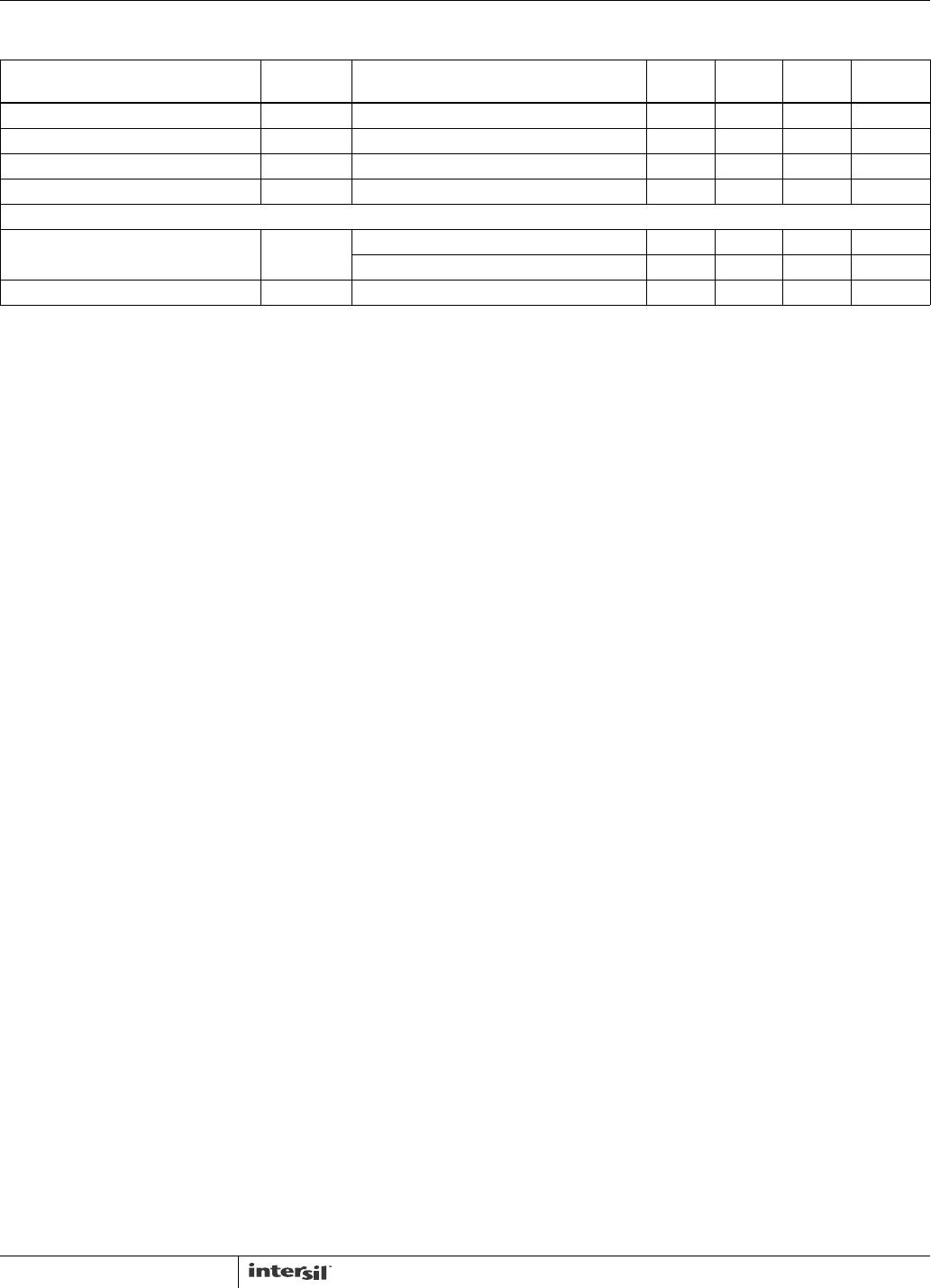
Upper Gate Source Impedance R
UG-SRCl
V
CC
= 4.25V; I = 50mA 3.5 Ω
Upper Gate Sink Impedance R
UG-SNKl
V
CC
= 4.25V; I = 50mA 2.7 Ω
Lower Gate Source Impedance R
LG-SRCl
V
CC
= 4.25V; I = 50mA 2.75 Ω
Lower Gate Sink Impedance R
LG-SNKl
V
CC
= 4.25V; I = 50mA 2.1 Ω
PROTECTION/DISABLE
OCSET Current Source I
OCSET
ISL6545C; LGATE/OCSET = 0V 19.5 21.5 23.5 µA
ISL6545I; LGATE/OCSET = 0V 18.0 21.5 23.5 µA
Disable Threshold (COMP/SD pin) V
DISABLE
0.375 0.400 0.425 V
NOTE:
7. Compliance to datasheet limits is assured by one or more methods: production test, characterization and/or design.
Electrical Specifications V
CC
= 12V, T
J
= 0 to +85°C. Boldface limits apply over the operating temperature range,
-40°C to +85°C. (Continued)
PARAMETER SYMBOL TEST CONDITIONS
MIN
(Note 7) TYP
MAX
(Note 7) UNITS
ISL6545, ISL6545A

