LTC2941
10
2941fb
For more information www.linear.com/LTC2941
applicaTions inFormaTion
The value of the external sense resistor is determined by
the maximum input range of V
SENSE
and the maximum
current of the application:
R
mV
I
SENSE
MAX
ʺ
50
The choice of the external sense resistor value influences
the gain of the coulomb counter. A larger sense resistor
gives a larger differential voltage between SENSE
+
and
SENSE
for the same current which results in more precise
coulomb counting. Thus the amount of charge represented
by the least significant bit (q
LSB
) of the accumulated charge
(registers C, D) is given by:
q
LSB
= 0.085mAh
50m
Ω
R
SENSE
M
128
or
q
LSB
= 0.085mAh
50mΩ
R
SENSE
when the prescaler is set to its default value of M=128.
Note that 1mAh = 3.6A • s = 3.6C (coulombs).
Choosing R
SENSE
= 50mV/I
MAX
is not sufficient in
applications where:
A.
the battery capacity (Q
BAT
) is very large compared to
the maximum current (I
MAX
):
Q
BAT
> I
MAX
• 5.5 hours
B. the battery capacity (Q
BAT
) is very small compared to
the maximum current (I
MAX
):
Q
BAT
< I
MAX
• 0.1 hours
For case A: In low current applications using a large bat-
tery, choosing R
SENSE
according to R
SENSE
= 50mV/I
MAX
can lead to a q
LSB
smaller than Q
BAT
/2
16
and the 16-bit
accumulated charge may underflow before the battery is
exhausted or overflow during charge. Choose in this case
a maximum R
SENSE
of:
R
SENSE
0.085mAh 2
16
Q
BAT
50mΩ
In an example application where the maximum current is
I
MAX
= 100mA, calculating R
SENSE
= 50mV/I
MAX
would
lead to a sense resistor of 500mΩ. This gives a q
LSB
of
8.5µAh and the accumulated charge register can represent
a maximum battery capacity of Q
BAT
= 8.5µAh • 65535 =
557mAh. If the battery is larger, R
SENSE
must be lowered.
For example, R
SENSE
must be reduced to 150mΩ if a bat-
tery with a capacity of 1800mAh is used.
For case B: In applications using a small battery but having
a high maximum current, q
LSB
can get quite large with
respect to the battery capacity. For example, if the battery
capacity is 100mAh and the maximum current is 1A, the
standard equation leads to choose a sense resistor value
of 50mΩ, resulting in:
q
LSB
= 0.085mAh = 306mC
The battery capacity then corresponds to only 1176 q
LSB
s
and less than 2% of the accumulated charge register is
utilized.
To preserve digital resolution in this case, the LTC2941
includes a programmable prescaler. Lowering the prescaler
factor M allows reducing q
LSB
to better match the accu-
mulated charge registers C and D to the capacity of the
battery
. The prescaling factor M can be chosen between 1
and its default value 128. The charge LSB then becomes:
q
LSB
= 0.085mAh
50m
Ω
R
SENSE
M
128
To use as much of the range of the accumulated charge
registers C and D as possible the prescaler factor M should
LTC2941
11
2941fb
For more information www.linear.com/LTC2941
be chosen for a given battery capacity Q
BAT
and a sense
resistor R
SENSE
as:
M128
Q
BAT
2
16
0.085mAh
R
SENSE
50mΩ
M can be set to 1, 2, 4, 8, …128 by programming B[5:3]
of the control register as M = 2
(4 • B[5] + 2 • B[4] + B[3])
. The
default value after power up is M = 128 = 2
7
(B[5:3] = 111).
In the above example of a 100mAh battery and a R
SENSE
of 50mΩ, the prescaler should be programmed to M = 4.
The q
LSB
then becomes 2.656µAh and the battery capacity
corresponds to roughly 37650 q
LSB
s.
Note that the internal digital resolution of the coulomb
counter is higher than indicated by q
LSB
. The digitized
charge q
INTERNAL
is M • 8 smaller than q
LSB
. q
INTERNAL
is
typically 299µAs for a 50mΩ sense resistor.
V
BAT
Alert B[7:6]
The V
BAT
alert function allows the LTC2941 to monitor
the voltage at SENSE
. If enabled, a drop of the voltage
at the SENSE
pin below a preset threshold is detected
and bit A[1] in the status register is set. If the alert mode
is enabled by setting B[2] to one, an alert is generated at
the AL/CC pin. The threshold for the V
BAT
alert function
is selectable according to Table 3.
Accumulated Charge Registers (C, D)
The coulomb counter of the LTC2941 integrates current
through the sense resistor. The 16-bit result of this charge
integration is stored in the accumulated charge registers
C and D. As the LTC2941 does not know the actual battery
status after initial power-up, the accumulated charge is
set to mid-scale (7FFFh). If the host knows the status of
the battery , the accumulated charge registers C[7:0] and
D[7:0] can be either programmed to the correct value via
I
2
C or it can be set after charging to FFFFh (full) by pulling
the AL/CC pin high (if charge complete mode is enabled
via bits B[2:1]). Before writing the accumulated charge
registers, the analog section should be shut down by setting
B[0] to 1. In order to avoid a change in the accumulated
charge registers between reading MSBs C[7:0] and LSBs
D[7:0], it is recommended to read them sequentially, as
shown in Figure 8.
Threshold Registers (E, F), (G, H)
For battery charge, the LTC2941 features a high and a
low threshold register. At power-up the high threshold
is set to FFFFh while the low threshold is set to 0000h.
Both thresholds can be programmed to a desired value via
I
2
C. As soon as the accumulated charge exceeds the high
threshold or falls below the low threshold, the LTC2941
sets the corresponding flag in the status register and pulls
the AL/CC pin low if alert mode is enabled.
I
2
C Protocol
The LTC2941 uses an I
2
C/SMBus compatible 2-wire open-
drain interface supporting multiple devices and masters on
a single bus. The connected devices can only pull the bus
wires LOW and they never drive the bus HIGH. The bus
wires should be externally connected to a positive sup
-
ply voltage via a current source or pull-up resistor. When
the bus is idle, both SDA and SCL are HIGH. Data on the
I
2
C-bus can be transferred at rates of up to 100kbit/s in
standard mode and up to 400kbit/s in fast mode.
Each device on the I
2
C/SMBus is recognized by a unique
address stored in that device and can operate as either a
transmitter or receiver, depending on the function of the
device. In addition to transmitters and receivers, devices
can also be classified as masters or slaves when perform
-
ing data transfers. A master is the device which initiates a
data
transfer
on the bus and generates the clock signals to
permit that transfer. At the same time any device addressed
is considered a slave. The LTC2941 always acts as a slave.
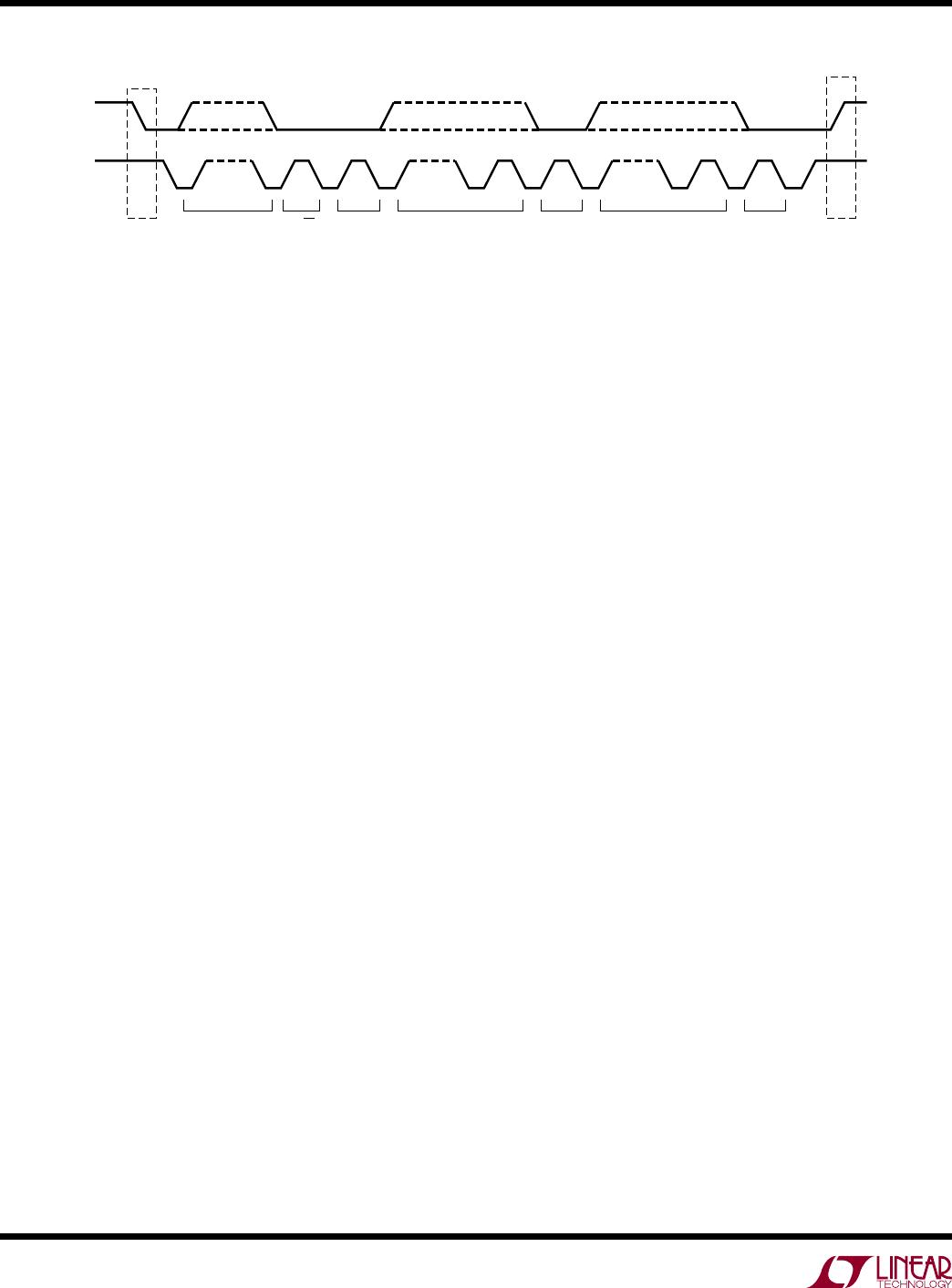
Figure 4 shows an overview of the data transmission on
the I
2
C bus.
applicaTions inFormaTion
LTC2941
12
2941fb
For more information www.linear.com/LTC2941
applicaTions inFormaTion
START and STOP Conditions
When the bus is idle, both SCL and SDA must be HIGH. A
bus master signals the beginning of a transmission with a
START condition by transitioning SDA from HIGH to LOW
while SCL is HIGH. When the master has finished com
-
municating with the slave, it issues a STOP condition by
transitioning SDA from LOW to HIGH while SCL is HIGH.
The bus is then free for another transmission. When the
bus is in use, it stays busy if a repeated START (Sr) is
generated instead of a STOP condition. The repeated START
(Sr) conditions are functionally identical to the START (S).
Data Transmission
After a START condition, the I
2
C bus is considered busy
and data transfer begins between a master and a slave. As
data is transferred over I
2
C in groups of nine bits (eight
data bits followed by an acknowledge bit), each group
takes nine SCL cycles. The transmitter releases the SDA
line during the acknowledge clock pulse and the receiver
issues an acknowledge (ACK) by pulling SDA LOW or
leaves SDA HIGH to indicate a not-acknowledge (NACK)
condition. Change of data state can only happen while
SCL is LOW.
Write Protocol
The master begins communication with a START condi
-
tion followed by the seven bit slave address 1100100
and the R/W
bit set to zero, as shown in Figure 5. The
LTC2941 acknowledges this by pulling SDA LOW and
then the master sends a command byte which indicates
which internal register the master is to write. The LTC2941
acknowledges and then latches the command byte into
its internal register address pointer. The master delivers
the data byte, the LTC2941 acknowledges once more and
latches the data into the desired register. The transmission
is ended when the master sends a STOP condition. If the
master continues by sending a second data byte instead
of a STOP, the LTC2941 acknowledges again, increments
its address pointer and latches the second data byte in
the following register, as shown in Figure 6.
Read Protocol
The master begins a read operation with a START condition
followed by the seven bit slave address 1100100 and the
R/W bit set to zero, as shown in Figure 7. The LTC2941
acknowledges and then the master sends a command
byte which indicates which internal register the master is
to read. The LTC2941 acknowledges and then latches the
command byte into its internal register address pointer.
The master then sends a repeated START condition fol
-
lowed by the same seven bit address with the R/W bit
now set to one. The LTC2941 acknowledges and sends
the contents of the requested register
. The transmission
is ended when the master sends a STOP condition. If
the master acknowledges the transmitted data byte, the
LTC2941 increments its address pointer and sends the
contents of the following register, as shown in Figure 8.
SCL
SDA
START
CONDITION
STOP
CONDITION
ADDRESS R/W ACK DATA ACK DATA ACK
1 - 7 8 9
2941 F04
a6 - a0 b7 - b0 b7 - b0
1 - 7 8 9 1 - 7 8 9
P
S
Figure 4. Data Transfer Over I
2
C or SMBus

LTC2941IDCB#TRMPBF

Mfr. #:
Manufacturer:
Analog Devices / Linear Technology
Description:
Battery Management Bat Gas Gauge w/ I2C Int
Lifecycle:
New from this manufacturer.
Delivery:
DHL FedEx Ups TNT EMS
Payment:
T/T Paypal Visa MoneyGram Western Union