LTC2941
7
2941fb
For more information www.linear.com/LTC2941
operaTion
Overview
The LTC2941 is a battery gas gauge device designed for
use with single Li-Ion cells and other battery types with
a terminal voltage between 2.7V and 5.5V. A precision
coulomb counter integrates current through a sense
resistor between the batterys positive terminal and the
load or charger.
Coulomb Counter
Charge is the time integral of current. The LTC2941 mea
-
sures battery current by monitoring the voltage developed
across a sense resistor and then integrates this information
to infer charge. The differential voltage between SENSE
+
and SENSE
is applied to an auto-zeroed differential analog
integrator to convert the measured current to charge.
When the integrator output ramps to REFHI or REFLO
levels, switches S1, S2, S3 and S4 toggle to reverse the
ramp direction. By observing the condition of the switches
and the ramp direction, polarity is determined.
A programmable prescaler is incremented or decremented
every time the integrator changes ramp direction. The
prescaler effectively increases integration time by a factor
M programmable from 1 to 128. At each under or overflow
of the prescaler, the accumulated charge is incremented or
decremented one count. The value of accumulated charge
is read via the I
2
C interface.
Power-Up Sequence
When V
SENSE
+
rises above a threshold of approximately
2.45V, the LTC2941 generates an internal power-on reset
(POR) signal and sets all registers to their default state.
In the default state, the coulomb counter is active. The
accumulated charge is set to mid-scale (7FFFh), the low
threshold registers are set to 0000h and all the high thresh
-
old registers are set to FFFFh. The alert mode is enabled
and the coulomb counter prescaling factor M is set to 128.
+
+
+
+
S4
REFHI
REFLO
S3
S2
S1
LOADCHARGER
SENSE
+
R
SENSE
BATTERY
I
BAT
SENSE
GND
POLARITY
DETECTION
CONTROL
LOGIC
PRE-
SCALER
M
I
2
C/
SMBus
REGISTERS
AL/CC
SCL
SDA
2941 F03
STATUS
CONTROL
ACR
THRESHOLDS
V
SUPPLY
Figure 3. Coulomb Counter Section of the LTC2941
LTC2941
8
2941fb
For more information www.linear.com/LTC2941
applicaTions inFormaTion
I
2
C/SMBus Interface
The LTC2941 communicates with a bus master using a
2-wire interface compatible with I
2
C and SMBus. The 7-bit
hard-coded I
2
C address of LTC2941 is 1100100.
The LTC2941 is a slave-only device. Therefore the serial
clock line (SCL) is input only while the data line (SDA) is
bidirectional. For more details refer to the I
2
C Protocol
section.
Internal Registers
The LTC2941 integrates current through a sense resistor
and stores a 16-bit result, accumulated charge, as two
bytes in registers C and D. Two byte high and low limits
programmed in registers E, F, G and H are continuously
compared against the accumulated charge. If either limit is
exceeded, a corresponding flag is set in the status register
bits A[2] or A[3]. If the alert mode is enabled, the AL/CC
pin pulls low.
The internal eight registers are organized as shown in
Table 1:
Table 1. Register Map
ADDRESS NAME REGISTER DESCRIPTION R/W DEFAULT
00h A Status R See Below
01h B Control R/W 3Ch
02h C Accumulated Charge MSB R/W 7Fh
03h D Accumulated Charge LSB R/W FFh
04h E Charge Threshold High MSB R/W FFh
05h F Charge Threshold High LSB R/W FFh
06h G Charge Threshold Low MSB R/W 00h
07h H Charge Threshold Low LSB R/W 00h
R = Read, W = Write
Status Register (A)
Table 2 shows the details of the status register (address
00h):
Table 2. Status Register A (Read Only)
BIT NAME OPERATION DEFAULT
A[7] Chip Identification 1: LTC2941
0: LTC2942
1
A[6] Reserved Not Used. 0
A[5]
Accumulated Charge
Overflow/Underflow
Indicates that the value of the
accumulated charge hit either
top or bottom.
0
A[4] Reserved Not used. 0
A[3] Charge Alert High Indicates that the accumulated
charge value exceeded the
charge threshold high limit.
0
A[2] Charge Alert Low Indicates that the accumulated
charge value dropped below
the charge threshold low limit.
0
A[1] V
BAT
Alert Indicates that the battery
voltage (at SENSE
) dropped
below selected V
BAT
threshold.
0
A[0] Undervoltage
Lockout Alert
Indicates recovery from
undervoltage. If equal to 1,
a UVLO has occurred and
the content of registers is
uncertain.
X
The AL/CC pin can be configured to pull low whenever any
status register bit is set (except for bit A[7] and A[0]), us-
ing control register bits B[2] and B[1]. All status register
bits except A[7] are cleared after being read by the host
if the conditions which set these bits have been removed.
As soon as one of the measured quantities exceeds the
programmed
limits,
the corresponding bit A[3], A[2] or
A[1] in the status register is set.
LTC2941
9
2941fb
For more information www.linear.com/LTC2941
applicaTions inFormaTion
Bit A[5] is set if the LTC2941’s accumulated charge over-
flows or underflows the combined total in registers C and D.
Note that the counting process does not roll over, but simply
stops at FFFFh or 0000h until the direction is reversed.
The LTC2941 includes a battery undervoltage monitor,
which sets bit A1 if the limit is exceeded. Limits are selected
in the control register.
The undervoltage lockout (UVLO) bit A[0] is set if, dur
-
ing operation, the voltage on SENSE
+
drops below 2.7V
without reaching the POR level. The analog parts of the
coulomb counter are switched off while the digital register
values are retained. After recovery of the supply voltage
the coulomb counter resumes integrating with the stored
value in the accumulated charge registers (C, D) but it has
missed any charge flowing while V
SENSE
+
< 2.7V.
The hard coded bit A[7] of the status register enables the
host to distinguish the LTC2941 from the pin compatible
LTC2942, allowing the same software to be used with
both devices.
Control Register (B)
The operation of the LTC2941 can be controlled by pro
-
gramming the control register at address 01h. Table 3
shows the organization of the 8-bit control register B[7:0]
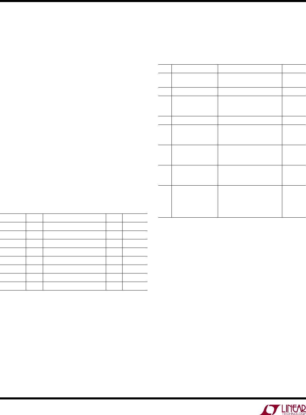
Table 3. Control Register B
BIT NAME OPERATION DEFAULT
B[7:6] V
BAT
Alert [11] Threshold Value = 3.0V.
[10] Threshold Value = 2.9V.
[01] Threshold Value = 2.8V.
[00] V
BAT
Alert Off.
[00]
B[5:3] Prescaler M Sets coulomb counter prescaling
factor M between 1 and 128.
Default is 128.
M = 2
(4 • B[5] + 2 • B[4] + B[3])
.
[111]
B[2:1] AL/CC
Configure
Configures the AL/CC pin.
[10] Alert Mode.
Alert functionality enabled.
Pin becomes logic output.
[01] Charge Complete Mode.
Pin becomes logic input and accepts
“charge complete” signal (e.g., from
a charger) to set accumulated charge
Register to FFFFh.
[00] AL
/CC pin disabled.
[11] Not allowed.
[10]
B[0] Shutdown Shut down analog section to reduce
I
SUPPLY
.
[0]
Power Down B[0]
Programming the last bit B[0] of the control register to 1
sets the analog parts of the LTC2941 in power down and
the current consumption drops typically below 1µA. All
analog circuits are disabled while the values in the registers
are retained. Note that any charge flowing while B[0] is 1
is not measured and the charge information below 1 LSB
of the accumulated charge register is lost.
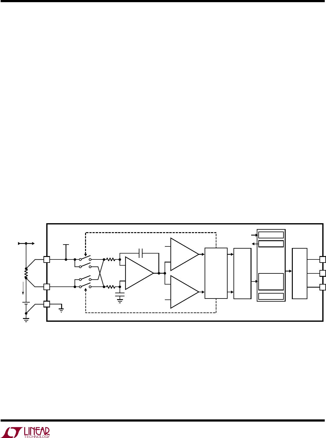
Alert/Charge Complete Configuration B[2:1]
The AL/CC pin is a dual function pin configured by the
control register. By setting bits B[2:1] to [10] (default)
the AL/CC pin is configured as an alert pin following the
SMBus protocol. In this alert mode the AL/CC pin is a digital
output and is pulled low if one of the measured quantities
exceeds its high or low threshold or if the an overflow/
underflow occurs in the accumulated charge registers C
and D. An alert response procedure started by the master
resets the alert at the AL/CC pin. For further information
see the Alert Response Protocol section.
Setting the control bits B[2:1] to [01] configures the AL/
CC pin as a digital input. In this mode, a high input on the
AL/CC pin communicates to the LTC2941 that the battery
is full and the accumulated charge is set to its maximum
value FFFFh. The AL/CC pin would typically be connected
to the “charge complete” output from the battery charger
circuitry.
If neither the alert nor the charge complete functionality
is desired, bits B[2:1] should be set to [00]. The AL/CC
pin is then disabled and should be tied to GND. Avoid set
-
ting B[2:1] to [11] as it enables the alert and the charge
complete modes simultaneously
.
Choosing R
SENSE
and Coulomb Counter
Prescaler “M” B[5:3]
To achieve the specified precision of the coulomb counter
the differential voltage between SENSE
+
and SENSE
must
stay within ±50mV. For differential input signals up to
±300mV the LTC2941 will remain functional but the preci
-
sion of the coulomb counter is not guaranteed.

LTC2941IDCB#TRMPBF

Mfr. #:
Manufacturer:
Analog Devices / Linear Technology
Description:
Battery Management Bat Gas Gauge w/ I2C Int
Lifecycle:
New from this manufacturer.
Delivery:
DHL FedEx Ups TNT EMS
Payment:
T/T Paypal Visa MoneyGram Western Union