MAX6952
4-Wire Interfaced, 2.7V to 5.5V,
4-Digit 5
7 Matrix LED Display Driver
________________________________________________________________ Maxim Integrated Products 1
For pricing, delivery, and ordering information, please contact Maxim/Dallas Direct! at
1-888-629-4642, or visit Maxim’s website at www.maxim-ic.com.
General Description
The MAX6952 is a compact cathode-row display driver
that interfaces microprocessors to 5
7 dot-matrix LED
displays through an SPI™-compatible serial interface.
The MAX6952 drives up to four digits (140 LEDs).
Included on chip are an ASCII 104-character font, mul-
tiplex scan circuitry, column and row drivers, and static
RAM that stores each digit, as well as font data for 24
user-definable characters. The segment current for the
LEDs is set by an internal digit-by-digit digital bright-
ness control.
The device includes a low-power shutdown mode, seg-
ment blinking (synchronized across multiple drivers, if
desired), and a test mode that forces all LEDs on. The
LED drivers are slew rate limited to reduce EMI.
For a 2-wire interfaced version, refer to the MAX6953
data sheet. An EV kit is available for the MAX6952.
Features
High-Speed 26MHz with SPI-/QSPI-™/
MICROWIRE™-Compatible Serial Interface
2.7V to 5.5V Operation
Drives Four Monocolor or Two Bicolor Cathode-
Row 5
7 Matrix Displays
Built-In ASCII 104-Character Font
24 User-Definable Characters Available
Automatic Blinking Control for Each Segment
36µA Low-Power Shutdown (Data Retained)
16-Step Digital Brightness Control
Display Blanked on Power-Up
Slew-Rate-Limited Segment Drivers for Lower EMI
36-Pin SSOP and 40-Pin DIP Packages
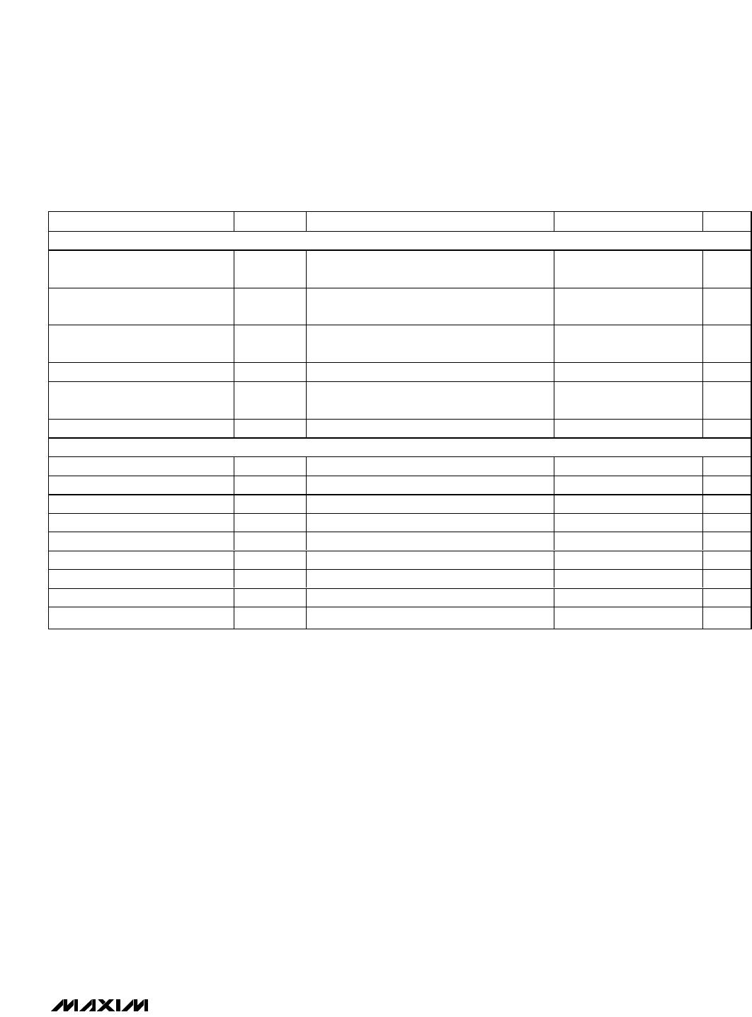
Ordering Information
DIGIT 1
R1
R6
R7
C1
R4
R3
R2
R5
C2
C3
C5
C4
DIGIT 0
O0
O1
O2
O3
O4
O5
O6
O14
O15
O16
O17
O18
R1
R6
R7
C1
R4
R3
R2
R5
C2
C3
C5
C4
O0
O1
O2
O3
O4
O5
O6
O19
O20
O21
O22
O23
R1
R6
R7
C1
R4
R3
R2
R5
C2
C3
C5
C4
O7
O8
O9
O10
O11
O12
O13
O14
O15
O16
O17
O18
R1
R6
R7
C1
R4
R3
R2
R5
C2
C3
C5
C4
DIGIT 3
O7
O8
O9
O10
O11
O12
O13
O19
O20
O21
O22
O23
DIGIT 2
3.3V
100nF
47µF
O0
O1
O2
O3
O4
O5
O6
O7
O8
O9
O10
O11
O12
O13
O14
O15
O16
O17
O18
O19
O20
O21
O22
O23
ISET
OSC
V+
V+
GND
GND
CS
GND
DIN
CLK
DOUT
C
SET
26pF
R
SET
53.6k
MAX6952
BLINK
3.3V
4.7k
Typical Application Circuit
19-2437; Rev 1; 10/02
EVALUATION KIT
AVAILABLE
PART TEMP RANGE PIN-PACKAGE
MAX6952EAX -40°C to +85°C 36 SSOP
MAX6952EPL -40°C to +85°C 40 PDIP
SPI and QSPI are trademarks of Motorola, Inc.
MICROWIRE is a trademark of National Semiconductor Corp.
Pin Configurations appear at end of data sheet.
Message Boards
Medical Equipment
Industrial Displays
Audio/Video
Equipment
Gaming Machines
Applications
MAX6952
4-Wire Interfaced, 2.7V to 5.5V,
4-Digit 5
7 Matrix LED Display Driver
2 _______________________________________________________________________________________
ABSOLUTE MAXIMUM RATINGS
DC ELECTRICAL CHARACTERISTICS
(Typical operating circuit, V+ = 3.0V to 5.5V, T
A
= T
MIN
to T
MAX
, unless otherwise noted.) (Note 1)
Stresses beyond those listed under “Absolute Maximum Ratings” may cause permanent damage to the device. These are stress ratings only, and functional
operation of the device at these or any other conditions beyond those indicated in the operational sections of the specifications is not implied. Exposure to
absolute maximum rating conditions for extended periods may affect device reliability.
Voltage (with respect to GND)
V+ .............................................................................-0.3V to +6V
All Other Pins................................................-0.3V to (V+ + 0.3V)
O0O13 Sink Current ....................................................... 500mA
O14O23 Source Current .................................................. 50mA
Continuous Power Dissipation (T
A
= +70°C)
36-Pin SSOP (derate 11.8mW/°C above +70°C) .....941.2mW
40-Pin PDIP (derate 16.7mW/°C above +70°C)........1333mW
Operating Temperature Range (T
MIN
, T
MAX
)......-40°C to +85°C
Junction Temperature......................................................+150°C
Storage Temperature Range .............................-65°C to +150°C
Lead Temperature (soldering, 10s) .................................+300°C
PARAMETER SYMBOL CONDITIONS MIN TYP MAX UNITS
Operating Supply Voltage V+ 2.7 5.5 V
T
A
= T
MIN
to T
MAX
100 µA
Shutdown Supply Current I
SHDN
Shutdown mode, all
digital inputs at V+ or
GND
T
A
= +25°C3680
Operating Supply Current I+
All segments on, intensity set to full,
internal oscillator, DOUT open circuit, no
display load connected, blink open circuit
12 16 mA
Master Clock Frequency (OSC
Internal Oscillator)
f
OSC
OSC = RC oscillator, R
SET
= 53.6k,
C
SET
= 26pF
4 MHz
Master Clock Frequency (OSC
External Oscillator)
f
OSC
OSC overdriven externally 1 8 MHz
Dead Clock Protection
Frequency
f
OSC
90 kHz
OSC Internal/External Detection
Threshold
V
OSC
1.7 V
OSC High Time t
CH
50 ns
OSC Low Time t
CL
50 ns
Slow Segment Blink Period
(OSC Internal Oscillator)
f
S L OWB L I N K
OSC = RC oscillator, R
SET
= 53.6k,
C
SET
= 26pF
1s
Fast Segment Blink Period
(OSC Internal Oscillator)
f
F A S T B L I N K
OSC = RC oscillator, R
SET
= 53.6k,
C
SET
= 26pF
0.5 s
Fast or Slow Segment Duty
Cycle
(Note 2) 49.5 50.5 %
Column Drive Source Current I
COLUMN
V
LED
= 2.4V, V+ = 3.0V, T
A
= +25°C -32 -48 mA
Segment Current Slew Rate I
SEG
/tT
A
= +25
o
C 12.5 mA/µs
Segment Drive Current
Matching (Within IC)
I
SEG
T
A
= +25
o
C4%
MAX6952
4-Wire Interfaced, 2.7V to 5.5V,
4-Digit 5
7 Matrix LED Display Driver
_______________________________________________________________________________________ 3
DC ELECTRICAL CHARACTERISTICS (continued)
(Typical operating circuit, V+ = 3.0V to 5.5V, T
A
= T
MIN
to T
MAX
, unless otherwise noted.) (Note 1)
Note 1: All parameters tested at T
A
= +25°C. Specifications over temperature are guaranteed by design.
Note 2: Guaranteed by design.
PARAMETER SYMBOL CONDITIONS MIN TYP MAX UNITS
LOGIC INPUTS AND OUTPUTS
Input High Voltage
DIN, CLK, CS
V
IH
2.4 V
Input Low Voltage
DIN, CLK, CS
V
IL
0.4 V
Input Leakage
DIN, CLK, CS, OSC
I
IH
, I
IL
-2 +0.1 +2 µA
DOUT Output Low Voltage V
OLDO
I
SINK
= 1.6mA 0.4 V
DOUT Output High Voltage V
OHDO
I
SOURCE
= 1.6mA
V+
- 0.4V
V
Blink Output Low Voltage V
OLBK
I
SINK
= 1.6mA 0.4 V
TIMING CHARACTERISTICS
(Figure 1)
CLK Clock Period t
CP
38.4 ns
CLK Pulse Width High t
CH
19 ns
CLK Pulse Width Low t
CL
19 ns
CS Fall to CLK Rise Setup Time t
CSS
9.5 ns
CLK Rise to CS Rise Hold Time t
CSH
5ns
DIN Setup Time t
DS
9.5 ns
DIN Hold Time t
DH
0ns
CS Pulse High t
CSW
19 ns
DOUT Propagation Delay t
DO
C
LOAD
= 10pF 19 ns

MAX6952EAX+

Mfr. #:
Manufacturer:
Maxim Integrated
Description:
LED Display Drivers 2.7-5.5V 4-Digit 5x7 Matrix LED Driver
Lifecycle:
New from this manufacturer.
Delivery:
DHL FedEx Ups TNT EMS
Payment:
T/T Paypal Visa MoneyGram Western Union

Products related to this Datasheet