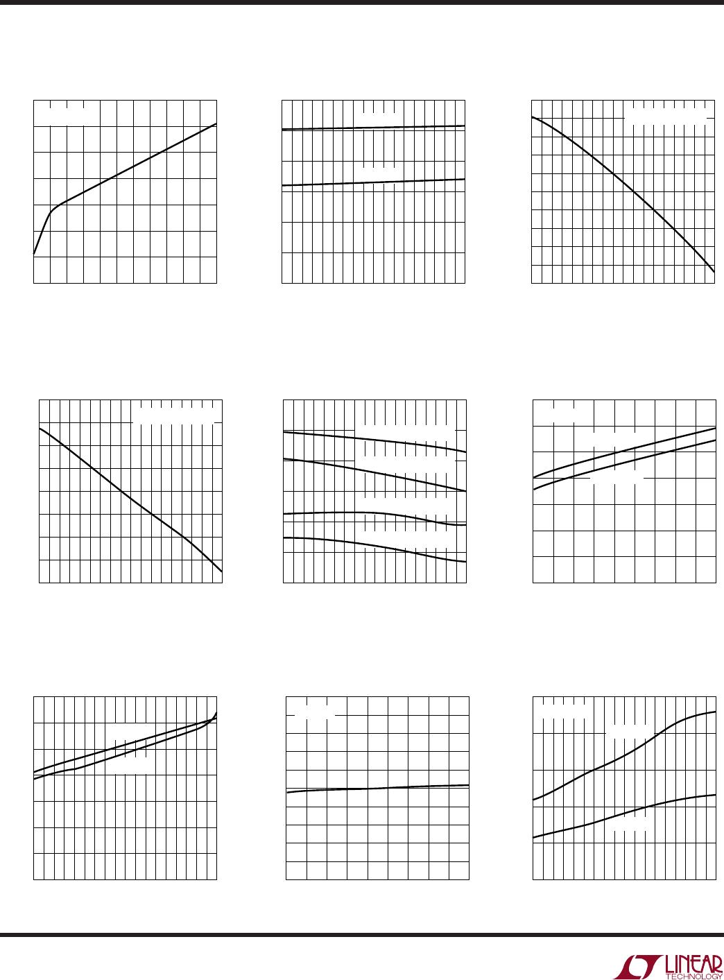
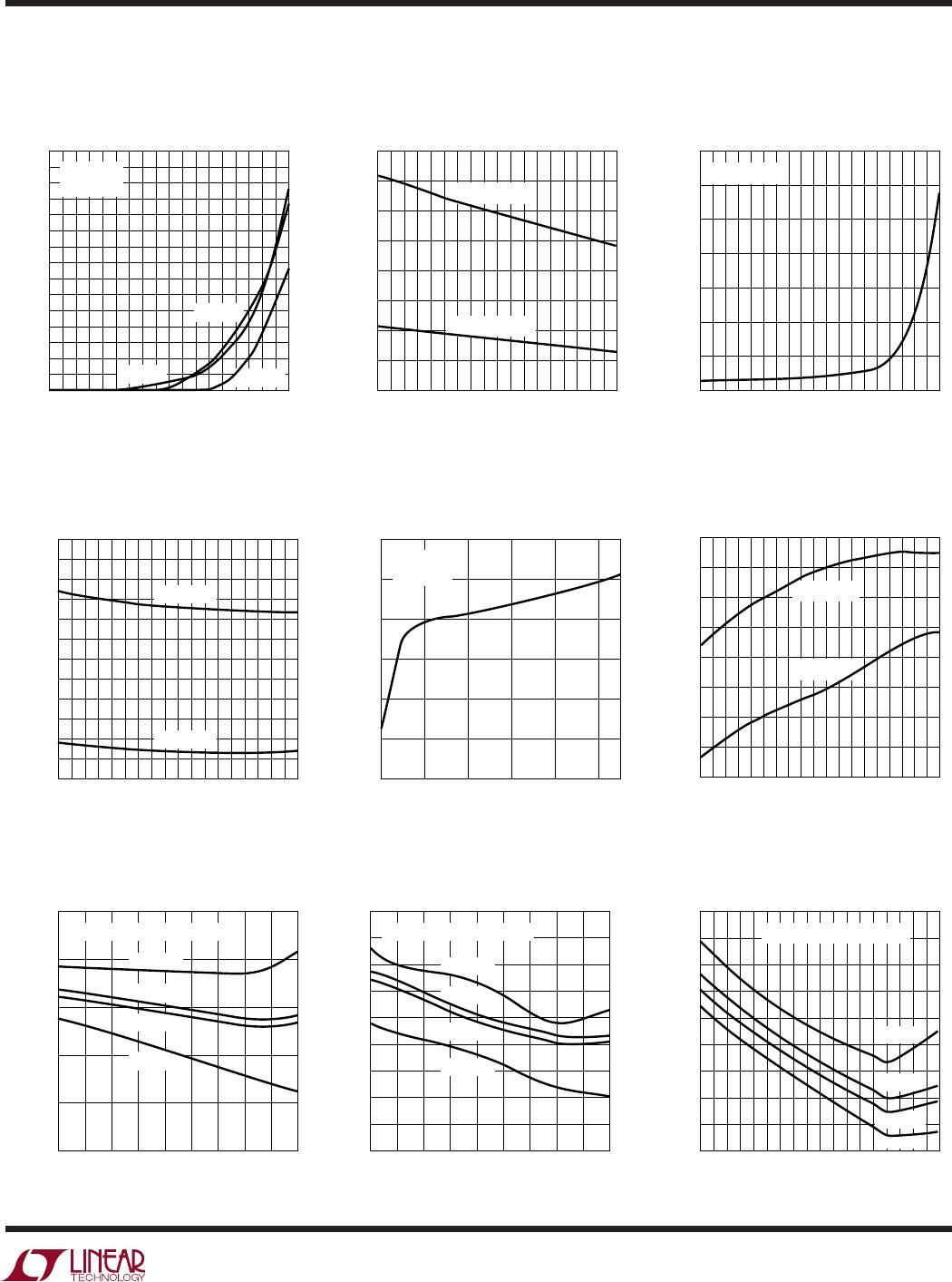
LTC1699 Series
4
TYPICAL PERFOR A CE CHARACTERISTICS
UW
Supply Current vs Supply Voltage
Supply Current vs Temperature
Resistance Between SENSE and FB
Pins vs Temperature (LTC1699-81)
SCL, SDA, SEL and VRON Input
High and Low Voltage vs
Temperature
SCL, SDA, SEL and VRON Input
High and Low Voltage vs Supply
Voltage
SCL, SDA, SEL and VRON
Hysteresis vs Temperature
SCL, SDA, SEL and VRON
Hysteresis vs Supply Voltage
SDA, CPU_ON, IO_ON, CLK_ON
Output Low Voltage vs
Temperature
V
CC
(V)
1.5
SUPPLY CURRENT (µA)
1699 G01
350
300
250
200
150
100
50
0
2 2.5 3 3.5 4 4.5 5 5.5 6 6.5 7
T
A
= 25°C
TEMPERATURE (°C)
SUPPLY CURRENT (µA)
1699 G02
300
250
200
150
100
50
0
–55 –35 –15 5 25 45 65 85 105 125
V
CC
= 5.5V
V
CC
= 2.7V
TEMPERATURE (°C)
R
SENSE
(k)
1699 G03
20.08
20.06
20.04
20.02
20.00
19.98
19.96
19.94
19.92
19.90
19.88
–55 –35 –15 5 25 45 65 85 105 125
V
CC
= 2.7V TO 5.5V
TEMPERATURE (°C)
INPUT HIGH AND LOW VOLTAGE (V)
1699 G04
1.40
1.35
1.30
1.25
1.20
1.15
1.10
–55 –35 –15 5 25 45 65 85 105 125
INPUT HIGH, V
CC
= 5.5V
INPUT LOW, V
CC
= 5.5V
INPUT HIGH, V
CC
= 2.7V
INPUT LOW, V
CC
= 2.7V
SUPPLY VOLTAGE (V)
INPUT HIGH AND LOW VOLTAGE (V)
1699 G05
1.5
1.4
1.3
1.2
1.1
1.0
0.9
0.8
2.5 3 3.5 4 4.5 5 5.5 6 6.5 7
INPUT HIGH
T
A
= 25°C
INPUT LOW
TEMPERATURE (°C)
HYSTERESIS (V)
1699 G06
0.07
0.06
0.05
0.04
0.03
0.02
0.01
0
–55 –35 –15 5 25 45 65 85 105 125
V
CC
= 5.5V
V
CC
= 2.7V
SUPPLY VOLTAGE (V)
HYSTERESIS (V)
1699 G07
0.10
0.09
0.08
0.07
0.06
0.05
0.04
0.03
0.02
0.01
0
2.5 3 3.5 4 4.5 5 5.5 6 6.5 7
T = 25°C
TEMPERATURE (°C)
OUTPUT LOW VOLTAGE (V)
1699 G08
0.25
0.20
0.15
0.10
0.05
0
–55 –35 –15 5 25 45 65 85 105 125
V
CC
= 2.7V
I
PIN
= 3mA
V
CC
= 5.5V
TEMPERATURE (°C)
R
SENSE
(k)
1699 G18
10.08
10.06
10.04
10.02
10.00
9.98
9.96
9.94
9.92
–55 –35 –15 5 25 45 65 85 105 125
V
CC
= 2.7V TO 5.5V
Resistance Between SENSE and
FB Pins vs Temperature
(LTC1699-80, LTC1699-82)
LTC1699 Series
5
TYPICAL PERFOR A CE CHARACTERISTICS
UW
SCL, SDA and SEL Input Current
vs Temperature
TEMPERATURE (°C)
INPUT CURRENT (nA)
1699 G09
15
14
13
12
11
10
9
8
7
6
5
4
3
2
1
0
–55 –35 –15 5 25 45 65 85 105 125
SCL PIN
SEL PIN
SDA PIN
V
CC
= 5.5V
V
PIN
= 5.5V
SDA, PGOOD, CPU_ON, IO_ON,
CLK_ON Sink Current vs
Temperature
PGOOD, CPU_ON, IO_ON,
CLK_ON Leakage Current vs
Temperature
VRON Pull-Up Current vs
Temperature
VRON Pull-Up Current vs Supply
Voltage
Power Good Low Duration vs
Temperature
LTC1699-80 Divider Error vs
Temperature
LTC1699-81 Divider Error vs
Temperature
LTC1699-82 Divider Error vs
Temperature
TEMPERATURE (°C)
SINK CURRENT (mA)
1699 G10
80
70
60
50
40
30
20
10
0
–55 –35 –15 5 25 45 65 85 105 125
V
CC
= 5.5V, I
SK2
V
CC
= 2.7V, I
SK1
TEMPERATURE (°C)
LEAKAGE CURRENT (nA)
1699 G11
7
6
5
4
3
2
1
0
–60 –40 –20 0 20 40 60 80 100 120
V
PIN
= 5.5V
TEMPERATURE (°C)
VRON PULL-UP CURRENT (µA)
1699 G12
2.50
2.45
2.40
2.35
2.30
2.25
2.20
2.15
2.10
2.05
2.00
1.95
1.90
–55 –35 –15 5 25 45 65 85 105 125
V
CC
= 5.5V
V
CC
= 2.7V
SUPPLY VOLTAGE (V)
1.5
VRON PULL-UP CURRENT (µA)
1699 G013
3.0
2.5
2.0
1.5
1.0
0.5
0
2.5 3.5 4.5 5.5 6.5
T
A
= 25°C
V
RON
= 0V
TEMPERATURE (°C)
DIVIDER ERROR (%)
1699 G15
0.05
0
0.05
0.10
0.15
0.20
–55 –35 –15 5 25 45 65 85 105 125
V
CC
= 2.7V (MINIMUM V
CC
)
CODE 31
CODE 15
CODE 16
CODE 0
TEMPERATURE (°C)
DIVIDER ERROR (%)
1699 G16
0.25
0.20
0.15
0.10
0.05
0
0.05
0.10
0.15
0.20
–55 –35 –15 5 25 45 65 85 105 125
V
CC
= 2.7V (MINIMUM V
CC
)
CODE 15
CODE 31
CODE 0
CODE 16
TEMPERATURE (°C)
POWER GOOD LOW DURATION (µs)
1699 G14
52.0
51.5
51.0
50.5
50.0
49.5
49.0
–60 –40 –20 0 20 40 60 80 100 120
V
CC
= 5.5V
V
CC
= 2.7V
TEMPERATURE (°C)
DIVIDER ERROR (%)
1699 G17
0.16
0.14
0.12
0.10
0.08
0.06
0.04
0.02
0
0.02
–55 –35 –15 5 25 45 65 85 105 125
V
CC
= 2.7V (MINIMUM V
CC
)
CODE 31
CODE 15
CODE 16
CODE 0
LTC1699 Series
6
Note: Pin numbers apply to 16-lead SSOP packages.
SEL (Pin 1): Register Select Input. A TTL compatible logic
input pin that is used to select 1 of 2 resistor divider
settings. SEL selects the setting in Register 0 if pulled low
and the setting in Register 1 if pulled high.
NC (Pin 2): Not connected.
SDA (Pin 3): SMBus Data Input/Output. SDA is a high
impedance input when address, command or data bits are
shifted in. It is an open drain, N-channel output when
acknowledging or sending data back to the microproces-
sor during read-back. It requires a pull-up resistor or
current source to V
CC
.
SCL (Pin 4): SMBus Clock Input. Data at the SDA pin is
latched into the LTC1699 at the rising edge of the clock and
is shifted out of the SDA pin at the falling edge of the clock.
SCL is a high impedance input pin. It is driven by the open
collector output of a microprocessor and requires a pull-
up resistor or current source to V
CC
.
VRON (Pin 5): Global Control Input. This TTL compatible
input pin is pulled up internally by a 2.5µA current source.
Pulling VRON low forces the open drain output pins
(CPU_ON, IO_ON, CLK_ON and PGOOD) to pull to ground.
If the LTC1699-80, LTC1699-81 or LTC1699-82 is pro-
grammed to turn on DC/DC converters, pulling VRON high
three-states the CPU_ON, IO_ON and CLK_ON pins and
allows the DC/DC converters to soft-start.
PGOOD (Pin 6): Power Good Output. This open drain
output is pulled low for 50µs each time the LTC1699-80,
LTC1699-81 or LTC1699-82 turns on the DC/DC convert-
ers or SEL is toggled to select a new code. PGOOD may be
connected to the FCB input of an LTC DC/DC converter to
force the converter into continuous mode operation. This
reduces the time needed for the converter output to settle
to a lower output voltage under light load conditions if the
SEL pin is toggled.
NC (Pin 7): Not connected.
CPU_ON (Pin 8): CPU DC/DC Converter Control. Open
drain output, usually connected to the RUN/SS pin of a DC/
DC converter that generates the CPU core supply. It pulls
low to shut down the converter or becomes a high imped-
ance state to allow the converter to soft-start.
IO_ON (Pin 9): I/O DC/DC Converter Control. Open drain
output, normally connected to the RUN/SS pin of the DC/
DC converter that generates the I/O supply. It pulls low to
shut down the converter or becomes a high impedance
state to allow the converter to soft-start.
CLK_ON (Pin 10): Clock DC/DC Converter Control. Open
drain output, optionally connected to the RUN/SS pin of
the DC/DC converter that generates the supply for the
clock buffer. It pulls low to shut down the converter or
becomes a high impedance state to allow the converter to
soft-start.
NC (Pin 11): Not connected.
SENSE (Pin 12): Sense Input. Upper terminal of the
resistor divider that is connected directly to the output
voltage being regulated.
FB (Pin 13): Feedback Input. Center tap of the divider that
is connected to the feedback pin of an LTC 0.8V referenced
DC/DC converter.
GND (Pin 14): Ground. Connect to regulator signal ground.
GND (Pin 15): Divider Ground. Short to Pin 14.
V
CC
(Pin 16): Positive Supply. 2.7V V
CC
5.5V. Bypass
this pin to ground with a 0.1µF ceramic capacitor.
PI FU CTIO S
UUU

LTC1699EMS8-81#TRPBF

Mfr. #:
Manufacturer:
Analog Devices / Linear Technology
Description:
Power Management Specialized - PMIC SMBus VID V Progmers
Lifecycle:
New from this manufacturer.
Delivery:
DHL FedEx Ups TNT EMS
Payment:
T/T Paypal Visa MoneyGram Western Union