Expand menu
Hello, Sign in
My Account
0
Cart
Home
Products
Sensors
Semiconductors
Passive Components
Connectors
Power
Electromechanical
Optoelectronics
Circuit Protection
Integrated Circuits - ICs
Main Products
Manufacturers
Blog
Services
About OMO
About Us
Contact Us
Check Stock
74LCX125YMTR
P1-P3
P4-P6
P7-P9
P10-P12
P13-P15
P16-P16
74LCX
125
Electrical characteristics
Doc ID 4980 Rev
8
7/16
T
a
bl
e
8.
A
C electric
al characteristics
Symbol
P
arameter
T
est conditi
on
V
alue
Unit
V
CC
(V)
C
L
(pF)
R
L
(
Ω
)
t
s
=
t
r
(ns
)
-40 to 85 °C
Min.
Max.
t
PLH
, t
PHL
Propagat
ion del
ay
tim
e
2.7
50
500
2.5
6.0
ns
3.0 t
o 3.6
1.0
5.2
t
PZL
, t
PZH
Output enab
le
time to HIGH and
LO
W le
vel
2.7
50
500
2.5
1.0
6.0
ns
3.0 t
o 3.6
1.0
5.0
t
PLZ
, t
PHZ
Output di
sabl
e
time to HIGH and
LO
W le
vel
2.7
50
500
2.5
1.0
6.0
ns
3.0 t
o 3.6
1.0
5.0
t
OSLH
t
OSHL
Outp
ut to
ou
tpu
t
ske
w ti
me
(1)
(2)
1.
Sk
ew is def
ined as
th
e abso
lute
valu
e of the d
iffer
ence
betwe
en th
e actu
al pr
opag
ation
del
ay fo
r
a
ny tw
o
out
puts of
the same
devic
e swit
ching in
the same
dir
ect
ion,
eit
her HIG
H or LOW
(t
OSL
H
= | t
PLHm
- t
PLHn
|,
t
OS
HL
= |
t
PH
Lm
- t
PHLn
|).
2.
Pa
ramet
er gu
aran
tee
d by des
ign.
3.0 t
o 3.6
50
500
2.5
1.0
ns
T
able 9.
Capacitive character
istics
Sy
m
bo
l
Para
m
et
er
T
est condit
i
on
V
alue
Unit
V
CC
(V)
T
A
= 25 °C
Min.
T
yp.
Max.
C
IN
Input cap
acitance
3.3
V
IN
= 0 to V
CC
5p
F
C
OUT
Outp
ut capaci
tance
3.3
V
IN
= 0 to V
CC
10
pF
C
PD
P
ower di
ssipati
on
capaci
t
anc
e
(1)
1.
C
PD
is d
ef
ine
d
as th
e
va
lue
of
the
I
C’s
in
te
rna
l e
quiv
a
len
t ca
pa
ci
ta
nce
w
hich
is
cal
c
ula
ted
fr
om t
he
oper
a
ting cu
r
re
nt cons
um
p
tio
n with
ou
t loa
d.
(R
ef
er to
Ta
bl
e 1
0:
Te
st
c
irc
uit
. A
ve
rag
e op
era
tin
g
cu
rre
nt
ca
n
be ob
ta
in
ed
by t
he
fo
ll
owi
ng eq
ua
ti
on
. I
CC(
op
r)
= C
PD
x V
CC
x f
IN
+ I
CC
/4 (pe
r g
ate).
3.3
f
IN
= 10 MHz
V
IN
= 0 or
V
CC
37
pF
Test c
ircui
t
74LCX125
8/16
Doc ID 4980
Rev
8
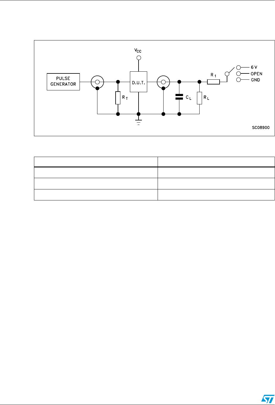
5 T
est
cir
cuit
Figur
e 4
.
T
est c
ircui
t
Note:
C
L
= 50 pF or
eq
uiv
alent (includes jig and probe
capacitanc
e)
R
L
= 500
Ω
or
equivalent
R
T
= Z
OUT
of pulse generator (typically 50
Ω
).
T
able
10.
T
est c
ircuit
Tes
t
S
w
i
t
c
h
t
PLH
, t
PHL
Open
t
PZL
, t
PLZ
6 V
t
PZH
, t
PHZ
GN
D
74LCX
125
Waveforms
Doc ID 4980 Rev
8
9/16
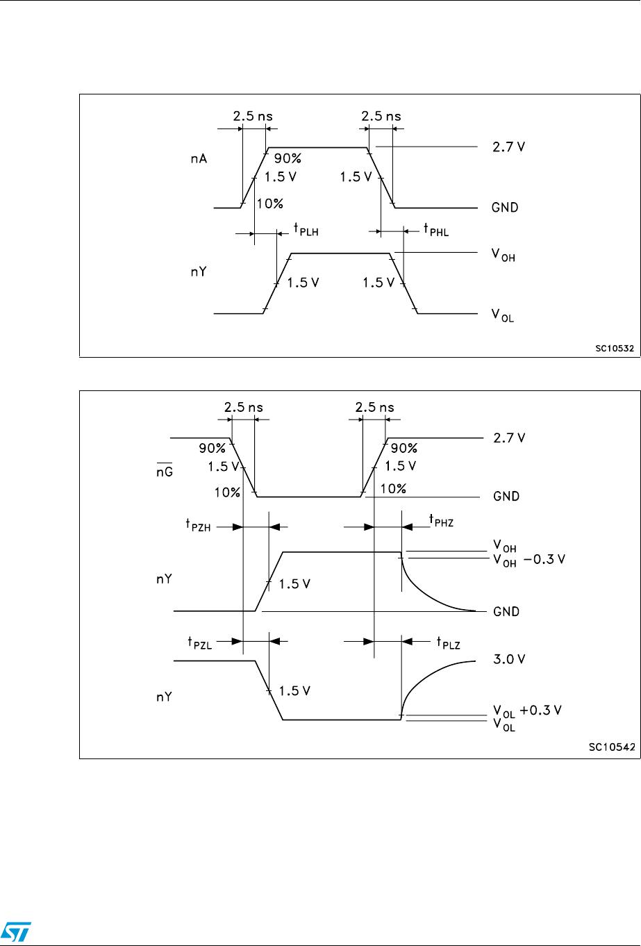
6 W
avef
orms
Figur
e 5
.
Propagat
ion
de
lay (f
= 1
M
Hz
; 50
% d
uty
cy
cl
e
)
Figure 6
.
Ou
tput ena
ble and d
isable ti
me (f
= 1 M
Hz; 50
% d
uty cycle)
P1-P3
P4-P6
P7-P9
P10-P12
P13-P15
P16-P16
74LCX125YMTR
Mfr. #:
Buy 74LCX125YMTR
Manufacturer:
STMicroelectronics
Description:
Buffers & Line Drivers Lo Vltg CMOS quad bus buffer (3-State)
Lifecycle:
New from this manufacturer.
Delivery:
DHL
FedEx
Ups
TNT
EMS
Payment:
T/T
Paypal
Visa
MoneyGram
Western
Union
Products related to this Datasheet
74LCX125YMTR
74LCX125YTTR
74LCX125TTR
74LCX125MTR