General Description
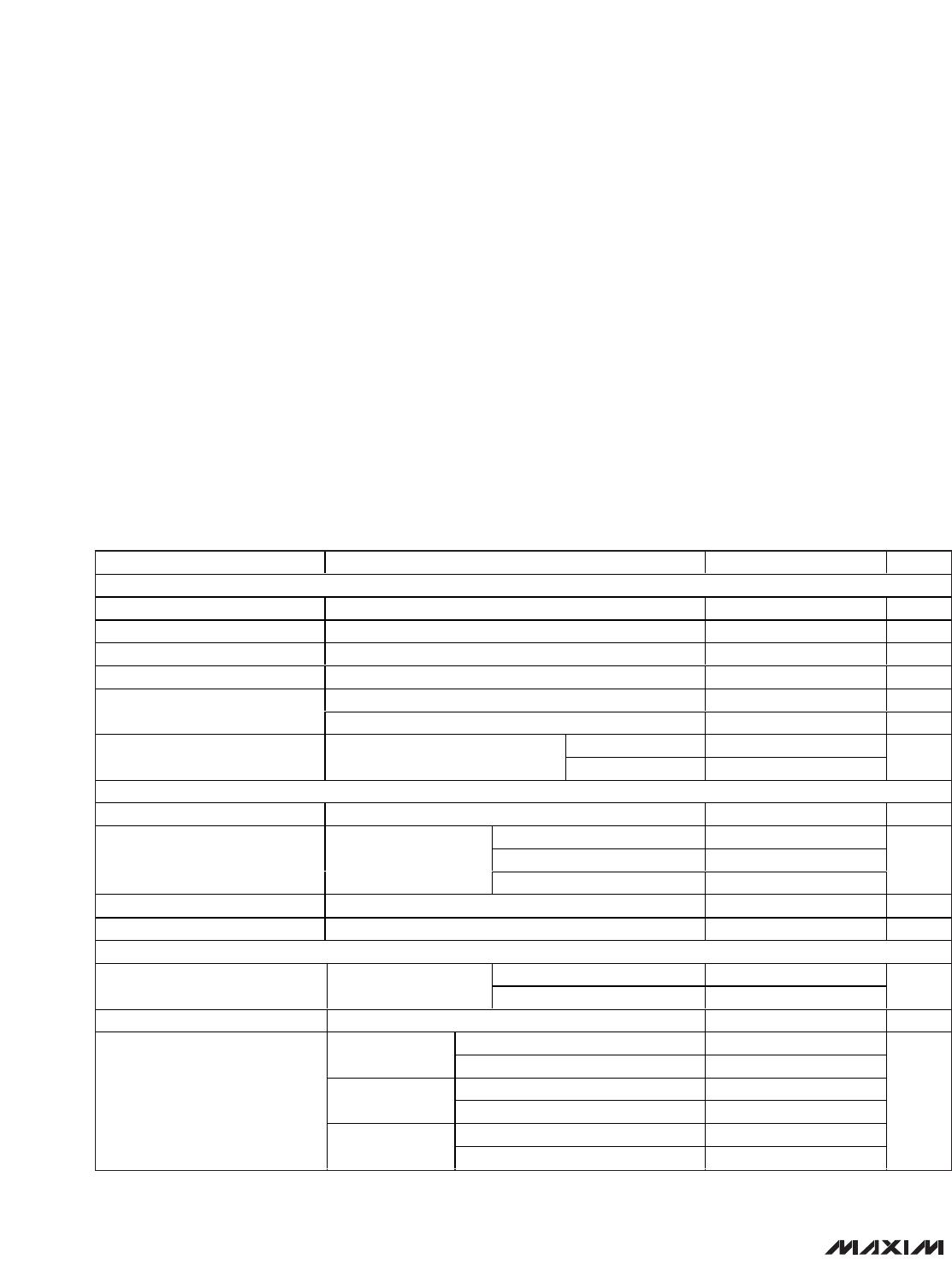
The MAX8606 complete 1-cell Li+ battery charge-man-
agement IC operates from either a USB port or AC
adapter. It integrates a battery disconnect switch, cur-
rent-sense circuit, PMOS pass element, and thermal-
regulation circuitry, while eliminating the external
reverse-blocking Schottky diode, to create a simple
and small charging solution. The charging sequence
initiates from power-OK indication, through prequalifi-
cation, fast-charge, top-off charge, and finally charg-
ing-complete indication for single-cell Li+ batteries.
Charging is controlled using constant current, constant
voltage, or constant die-temperature (CCCVCT
J
) regu-
lation for safe operation in handhelds.
Two logic inputs (EN1 and EN2) select suspend mode,
100mA, 500mA, or 1A input current limits to suit USB
requirements. Proprietary thermal-regulation circuitry
limits the die temperature to +100°C to prevent exces-
sive heat on the system PC board. Additional safety
features include an NTC thermistor input (THM) and
internal timers to protect the battery. A 3.5V to 4.2V SYS
output, in conjunction with the low-R
DSON
battery
switch, powers the system even when the battery is
deeply discharged or not installed. The IC also offers a
+3.3V/500µA output (VL), a charging status flag (CHG),
and an input-supply detection flag (POK). The
MAX8606 operates from a +4.25V to +5.5V supply and
includes undervoltage lockout below +3.4V and over-
voltage protection up to +14V.
Applications
Cellular Phones, Smartphones, PDAs
Digital Cameras, MP3 Players
USB Appliances, Charging Cradles and Docks
Features
Small 3mm x 3mm Thermally Enhanced TDFN
Package (0.8mm max height)
USB-Compliant Suspend Mode (20µA)
Selectable 100mA, 500mA, and Up to 1A Input
Current Limits
USB or AC Adapter Input
+6V to +14V Input Overvoltage Protection
Input UVLO Below +4V Rising (3.5V Falling)
Automatic Current Sharing Between Battery
Charging and System
Die Temperature Regulation (+100°C)
Prequal, Fast-Charge, and Top-Off Timers
Low Dropout Voltage, 250mV at 0.5A
NTC Thermistor Input
Charge Status and Input-Supply Detection Flags
MAX8606
USB/AC Adapter, Li+ Linear Battery Charger
with Integrated 50m
Ω
Battery Switch in TDFN
________________________________________________________________
Maxim Integrated Products
1
42
BAT
1
BAT
3
IN
VL
THM
5
CHG
6
POK
7
EN2
9
TMR
8
EN1
10
GND
11
SETI
12
SYS
13
SYS
14
MAX8606
TOP VIEW
TDFN
+
Pin Configuration
Ordering Information
19-3795; Rev 1; 12/08
For pricing, delivery, and ordering information, please contact Maxim/Dallas Direct! at
1-888-629-4642, or visit Maxim’s website at www.maxim-ic.com.
EVALUATION KIT
AVAILABLE
PART TEMP RANGE PIN-PACKAGE
TOP
MARK
MAX8606ETD+ -40°C to +85°C
14 TDFN 3mm x
3mm (T1433-1)
AAF
IN
BAT
GND
EN1
EN2
TMR
POK
CHG
SETI
SYS
THM
VL
USB/AC-ADAPTER
OVP UP TO 14V
Li+
3.5V TO 4.2V
STAND-ALONE
INPUT
CURRENT
SELECTION
STATUS
INDICATORS
MAX8606
μP
0.1μF
CONTROL
Typical Operating Circuit
+
Denotes lead-free/RoHS-compliant package.
MAX8606
USB/AC Adapter, Li+ Linear Battery Charger
with Integrated 50m
Ω
Battery Switch in TDFN
2 _______________________________________________________________________________________
ABSOLUTE MAXIMUM RATINGS
Stresses beyond those listed under “Absolute Maximum Ratings” may cause permanent damage to the device. These are stress ratings only, and functional
operation of the device at these or any other conditions beyond those indicated in the operational sections of the specifications is not implied. Exposure to
absolute maximum rating conditions for extended periods may affect device reliability.
IN to GND .............................................................. -0.3V to +16V
BAT, SYS, EN1, EN2, POK, CHG, TMR to GND.......-0.3V to +6V
VL, SETI, THM to GND .............................................-0.3V to +4V
SYS to BAT ...............................................................-0.3V to +6V
VL to IN...................................................................-16V to +0.3V
IN to BAT Current ...........................................................1.0A
RMS
IN to SYS Current ...........................................................1.0A
RMS
BAT to SYS Current ........................................................1.0A
RMS
BAT Short-Circuit Duration .........................................Continuous
Continuous Power Dissipation (T
A
= +70°C)
14-Pin 3mm x 3mm TDFN (derate 24.4mW/°C
above +70°C)..........................................................1951.2mW
Operating Temperature Range ...........................-40°C to +85°C
Junction Temperature Range ............................-40°C to +150°C
Storage Temperature Range .............................-65°C to +150°C
Lead Temperature (soldering, 10s) .................................+300°C
ELECTRICAL CHARACTERISTICS
(V
IN
= 5.0V, V
BAT
= 3.3V, EN1 = EN2 = GND, R
SETI
= 23.58kΩ, C
VL
= 0.1µF, C
SYS
= 4.7µF, T
A
= -40°C to +85°C, unless otherwise
noted. Typical values are at T
A
= +25°C.) (Note 1)
PARAMETER CONDITIONS MIN TYP MAX UNITS
IN
IN Voltage Range 014V
IN Operating Voltage Range (Note 2) 4.25 5.50 V
IN Undervoltage Threshold V
IN
rising, 500mV hysteresis (typ) 3.9 4.0 4.1 V
IN Overvoltage Threshold V
IN
rising, 100mV hysteresis (typ) 5.6 5.8 6.0 V
Charging, I
BAT
= I
SYS
= 0mA 1.2 3.0 mA
IN Supply Current
Suspend, EN1 = EN2 = high, I
VL
= 0mA 20 40 µA
T
A
= +25°C 0.1 10
IN to BAT Switch Leakage V
IN
= 14V, BAT = GND
T
A
= +85°C 0.5
µA
SYS
SYS Regulated Voltage I
SYS
= 0mA, V
BAT
= 3.3V 3.4 3.5 3.6 V
EN1 = low, EN2 = low 90 95 100
EN1 = low, EN2 = high 450 475 500
SYS Current Limit V
SYS
= 3.3V
EN1 = high, EN2 = low 675 712 750
mA
SYS Dropout Voltage (V
IN
- V
BAT
)I
SYS
= 400mA, V
SYS
= 3.3V, EN1 = low, EN2 = high 350 700 mV
SYS Load Regulation I
SYS
= 1mA to 675mA, EN1 = high, EN2 = low 10 mV
BAT
T
A
= +25°C 4.18 4.20 4.22
BAT Regulation Voltage I
BAT
= 0mA
T
A
= -40°C to +85°C 4.16 4.20 4.24
V
Maximum Charging Current 1 A
I
SYS
= 0mA 87 95 100
EN1 = low,
EN2 = low
I
SYS
= 50mA 45
I
SYS
= 0mA 450 475 500
EN1 = low,
EN2 = high
I
SYS
= 250mA 225
I
SYS
= 0mA 675 712 750
BAT Charging Current
EN1 = high,
EN2 = low
I
SYS
= 375mA 337
mA
MAX8606MAX8606
USB/AC Adapter, Li+ Linear Battery Charger
with Integrated 50m
Ω
Battery Switch in TDFN
_______________________________________________________________________________________ 3
ELECTRICAL CHARACTERISTICS (continued)
(V
IN
= 5.0V, V
BAT
= 3.3V, EN1 = EN2 = GND, R
SETI
= 23.58kΩ, C
VL
= 0.1µF, C
SYS
= 4.7µF, T
A
= -40°C to +85°C, unless otherwise
noted. Typical values are at T
A
= +25°C.) (Note 1)
PARAMETER CONDITIONS MIN TYP MAX UNITS
EN1 = low, EN2 = low, I
SYS
= 0mA 87 95 100
EN1 = low, EN2 = high, I
SYS
= 0 to
350mA
95
BAT Prequal Current V
BAT
= 2.0V
EN1 = high, EN2 = low, I
SYS
= 0 to
575mA
95
mA
Soft-Start Time 1.5 ms
BAT Prequal Threshold V
BAT
rising, 150mV hysteresis (typ) 2.9 3.0 3.1 V
BAT Dropout Voltage (V
IN
- V
BAT
)V
BAT
= 4.1V, I
BAT
= 400mA 200 400 mV
BAT Short-Circuit Current Limit BAT = GND 70 95 120 mA
BAT to SYS Switch R
ON
V
BAT
= 3.5V, V
SYS
= 3.4V, V
IN
= 0V 50 100 mΩ
BAT to SYS Switch Threshold BAT rising, 160mV hysteresis (typ) 3.4 3.5 3.6 V
Battery-Removal Threshold BAT rising, 210mV hysteresis (typ) 4.5 4.75 5.0 V
T
A
= +25°C 0.1 10
V
IN
= 0V
T
A
= +85°C 0.1
T
A
= +25°C 0.1 10
V
IN
= 2.4V
T
A
= +85°C 0.1
T
A
= +25°C -10 0.1 +10
BAT Leakage Current
EN1 = high, EN2 = high
T
A
= +85°C 0.1
µA
VL
VL Output Voltage I
VL
= 0 to 500µA 3.1 3.3 3.5 V
VL Shutdown Voltage V
EN1
= V
EN2
= 5V 0 V
THM
THM Internal Pullup Resistance 10 kΩ
THM Resistance Threshold, Hot 10% hysteresis 3.72 3.93 4.13 kΩ
THM Resistance Threshold, Cold 10% hysteresis 26.6 28.3 30.0 kΩ
THM Resistance Threshold,
Disabled
70% hysteresis 274 305 336 Ω
SETI
EN1 = low, EN2 = low 0.28
EN1 = low, EN2 = high 1.4SETI Servo Voltage
EN1 = high, EN2 = low 2.1
V
SETI Resistance Range 17.68 23.58 35.36 kΩ
POK
V
IN
rising 150 250 350
POK Trip Threshold (V
IN
- V
BAT
)
4.1V < V
IN
< 5.6V,
V
BAT
= 4.1V
V
IN
falling 5 55 125
mV
POK Voltage, Low I
POK
= 5mA 0.05 0.2 V
T
A
= +25°C 0.01 1
POK Leakage Current, High V
POK
= 6V
T
A
= +85°C 0.01
µA

MAX8606ETD+T

Mfr. #:
Manufacturer:
Maxim Integrated
Description:
Battery Management USB/AC Adapter Li+ Linear Bat Charger
Lifecycle:
New from this manufacturer.
Delivery:
DHL FedEx Ups TNT EMS
Payment:
T/T Paypal Visa MoneyGram Western Union

Products related to this Datasheet