MAX8606
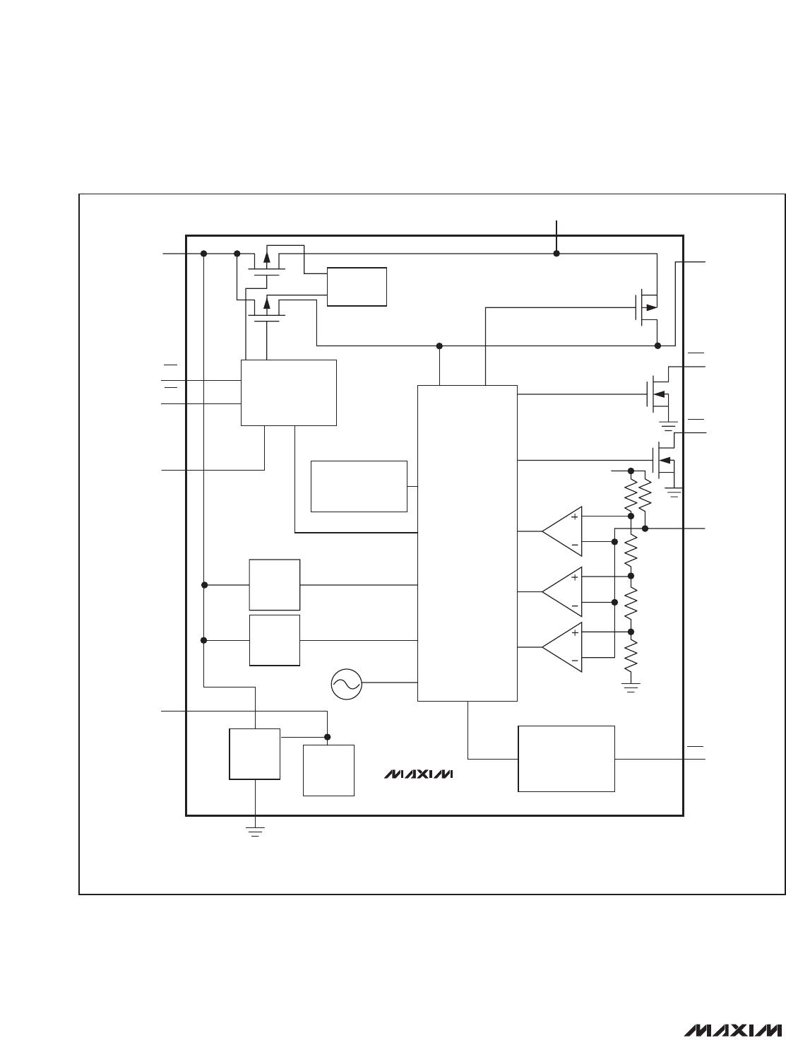
VL Internal Voltage Regulator
The MAX8606 linear charger contains an internal linear
regulator to supply the power for the IC. Bypass VL to
GND with a 0.1µF ceramic capacitor. VL is regulated to
3.3V whenever the input voltage is above the battery
voltage and can source up to 500µA for external loads.
CHG Charge-Indicator Output
CHG is an open-drain output that indicates charger sta-
tus and can be used with an LED. CHG goes low dur-
ing charging. CHG goes high impedance when V
BAT
equals 4.2V and the charging current drops below
50mA. When the MAX8606 is used in conjunction with a
microprocessor (µP), connect a pullup resistor between
CHG and the logic I/O voltage to indicate charge status
to the µP. CHG also indicates a timer fault. If the inter-
nal prequal or fast-charge timer expires without com-
pleting the charge cycle, charging is suspended and
the CHG output “blinks” at 2.1Hz.
Soft-Start
To prevent input transients, the rate of change of the
charge current is limited when the charger is turned on
or changes its current compliance. It takes approxi-
mately 1ms for the charger to go from 0mA to the maxi-
mum fast-charge current.
TMR
Input
The MAX8606 includes a 30-minute prequalification
fault timer, an 8-hour fast-charge fault timer, and a 30-
minute top-off timer to terminate the changing cycle.
Drive TMR low to enable the internal timers. Drive TMR
high to disable the internal timers and allow an external
device to determine charge times.
THM Input
The MAX8606 monitors the battery temperature with an
external NTC thermistor that is in close thermal contact
with the battery. Select a thermistor resistance that is
10kΩ at +25°C and has a beta of 3500 Kelvins. The IC
compares the resistance from THM to GND and sus-
pends charging when it is greater than 28.3kΩ or less
than 3.93kΩ, which translates to a battery temperature
of 0°C or +50°C, respectively. Connect THM to GND to
disable the temperature control function.
SYS Output
The MAX8606 contains a SYS output that delivers up to
1A
RMS
at 3.5V to 4.2V to power an external system.
Bypass SYS to GND with a 4.7µF or larger ceramic
capacitor. When V
BAT
exceeds 3.5V or when the
MAX8606 is in suspend mode, the MAX8606 internally
connects SYS to BAT through a 50mΩ switch. When
charging a battery, the load on SYS is serviced first and
the remaining available current goes to charge the bat-
tery. SYS is connected to BAT when V
IN
is not valid.
POK
The MAX8606 contains an open-drain POK output that
goes low when a valid input source is detected at IN. A
valid input source is one whose voltage is between 4V
and 5.8V and exceeds the battery voltage by 250mV.
After a valid input has been established, charging is
sustained with inputs as low as 3.5V as long as the
input voltage remains above the battery voltage by at
least 55mV. POK is high impedance otherwise.
Applications Information
Charge-Current Selection
For USB applications, the charging current is internally
limited to 100mA or 500mA. For wall-cube applications
requiring a different current requirement, set the charg-
ing current with an external resistor from SETI to GND
(R
SETI
). Calculate R
SETI
as follows:
R
SETI
= 8000 x 2.1V / (I
BAT
+ I
SYS
)
where EN1 = high and EN2 = low.
The SETI input also enables the user to monitor the
charging current. Under fast-charge operation, the
SETI voltage regulates to 1.4V (EN1 low and EN2 high)
or 2.1V (EN1 high and EN2 low). As the charging cur-
rent decreases, V
SETI
decreases. This is due to either
the thermal regulation control or voltage regulation con-
trol (4.2V) of the MAX8606. V
SETI
is calculated using
the following equation:
V
SETI
= (I
BAT
+ I
SYS
) x R
SETI
/ 8000
Thermal Regulation
The MAX8606 features a thermal limit that reduces the
charge current when the die temperature exceeds
+100°C. As the temperature increases, the IC lowers
the charge current by 50mA/°C above +100°C.
Capacitor Selection
Connect a ceramic capacitor from SYS to GND as
close to the IC as possible for proper stability. Use a
4.7µF X5R ceramic capacitor for most applications.
MAX8606
USB/AC Adapter, Li+ Linear Battery Charger
with Integrated 50m
Ω
Battery Switch in TDFN
_______________________________________________________________________________________ 9