MAX8606
Connect a 4.7µF ceramic capacitor from IN to GND as
close to the IC as possible. Use a larger input bypass
capacitor to reduce supply noise.
Thermal Considerations
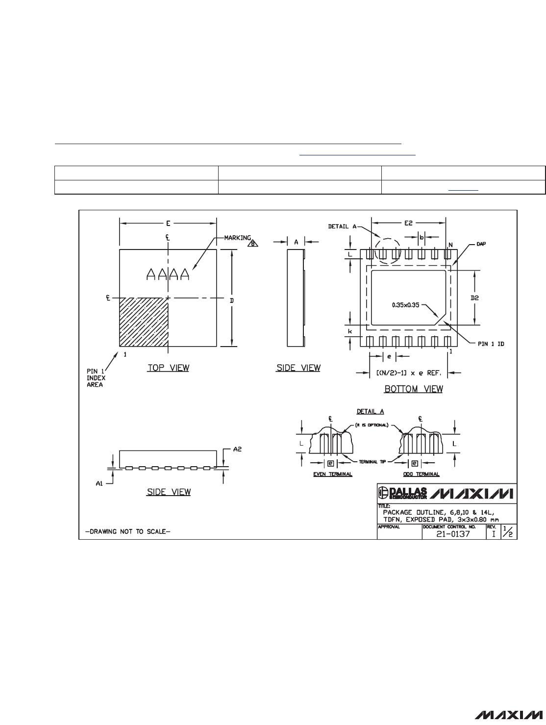
The MAX8606 is available in a thermally enhanced
TDFN package with exposed paddle. Connect the
exposed paddle to a large copper ground plane to pro-
vide a good thermal contact between the device and
the circuit board. The exposed paddle transfers heat
away from the device, allowing the MAX8606 to charge
the battery with maximum current while minimizing the
increase in die temperature.
DC Input Sources
The MAX8606 operates from well-regulated DC
sources. The full-charging input voltage range is 4.25V
to 5.8V. The device survives input voltages up to 14V
without damage to the IC. If V
IN
is greater than 5.8V
(typ), the IC stops charging. An appropriate power sup-
ply must provide at least 4.25V when sourcing the
desired peak charging current. It also must stay below
5.8V when unloaded.
Application Circuits
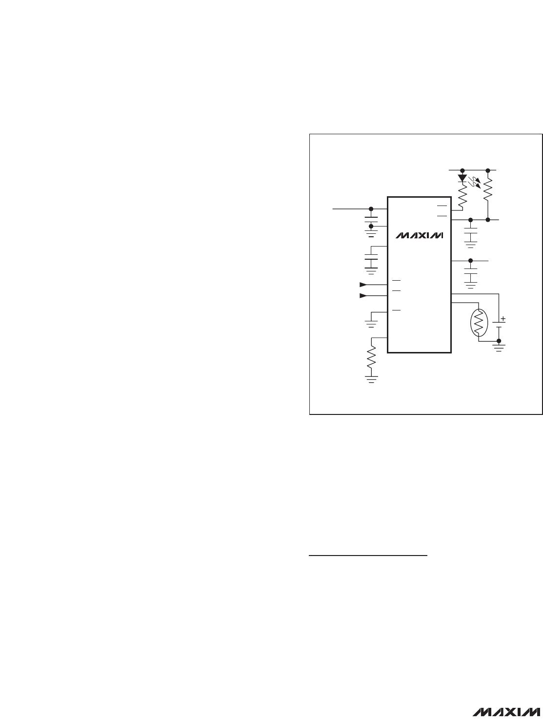
Stand-Alone Li+ Charger
The MAX8606 provides a complete Li+ charging solu-
tion. Figure 3 shows the MAX8606 as a stand-alone Li+
battery charger. The 23.58kΩ resistor connected to
SETI sets a charging current of 712mA (typ). The LED
indicates when either prequal or fast-charging has
begun. When the battery is charged the LED turns off.
USB Application with AC Adapter
The MAX8606 can be configured for USB applications
with an optional AC-adapter input (Figure 4). The p-
channel MOSFET disconnects the USB port when the
AC adapter is installed. Alternately, the USB port and
AC adapter may be excluded from each other by
mechanical means, such as using a single connector.
USB-Powered Li+ Charger
The universal serial bus (USB) provides a high-speed
serial communication port, as well as power for the
remote device. The MAX8606 can be configured to
charge a battery at the highest current possible from
the host port. Figure 5 shows the MAX8606 as a USB
battery charger. To make the circuit compatible with
either 100mA or 500mA USB ports, the system software
begins at 100mA charging current. The microprocessor
then enumerates with the host to determine its current
capability. If the host port is capable, the charging cur-
rent is increased to 475mA to avoid exceeding the
500mA USB specification.
Layout and Bypassing
Place the input capacitor as close to the device as pos-
sible. Provide a large copper ground plane to allow the
exposed paddle to sink heat away from the device.
Connect the battery to BAT as close to the device as
possible to provide accurate battery voltage sensing.
Make all high-current traces short and wide to minimize
voltage drops. A sample layout is available in the
MAX8606 evaluation kit to help speed designs.
Chip Information
PROCESS: BiCMOS
USB/AC Adapter, Li+ Linear Battery Charger
with Integrated 50m
Ω
Battery Switch in TDFN
10 ______________________________________________________________________________________