1©2018 Integrated Device Technology, Inc. May 30, 2018
Description
The 9FGV1005 is a member of IDT's PhiClock™ programmable
clock generator family. The 9FGV1005 provides two copies of a
single non-spread spectrum output frequency and one copy of the
crystal reference input. Two select pins allow for hardware
selection of the desired configuration, or two I
2
C bits allow easy
software selection of the desired configuration. The user may
configure any one of the four OTP configurations as the default
when operating in I
2
C mode. Four unique I
2
C addresses are
available, allowing easy I
2
C access to multiple components.
Typical Applications
HPC
Storage
10G/25G Ethernet
Fiber Optic Modules
SSDs
NVLink
Output Features
1 integer output frequency per configuration
2 programmable output pairs plus 1 LVCMOS REF output
10MHz–325MHz output frequency (LVDS or LP-HCSL)
10MHz–200MHz output frequency (LVCMOS)
Features
1.8V to 3.3V operation
Individual 1.8V to 3.3V V
DDO
for each programmable output
pair
Supports HCSL, LVDS and LVCMOS I/O standards
Supports LVPECL and CML logic with easy AC coupling – see
application note AN-891
for alternate terminations
HCSL utilizes IDT's LP-HCSL technology for improved
performance, lower power and higher integration:
Programmable output impedance of 85 or 100
On-board OTP supports up to 4 complete configurations
Configuration selected via strapping pins or I
2
C
< 100mW at 1.8V, < 200mW at 3.3V (LP-HCSL outputs running
at 100MHz)
4 programmable I
2
C addresses: D0/D1, D2/D3, D4/D5, D6/D7
read/write
Supported by IDT Timing Commander™ software
3 × 3 mm 16-LGA with integrated crystal option (9FGV1005Q)
Key Specifications
259fs rms typical phase jitter outputs at 156.25MHz (12kHz–
20MHz)
PCIe Gen1–4 compliant
PCIe Clocking Architectures
Common Clocked (CC)
Independent Reference without spread spectrum (SRnS)
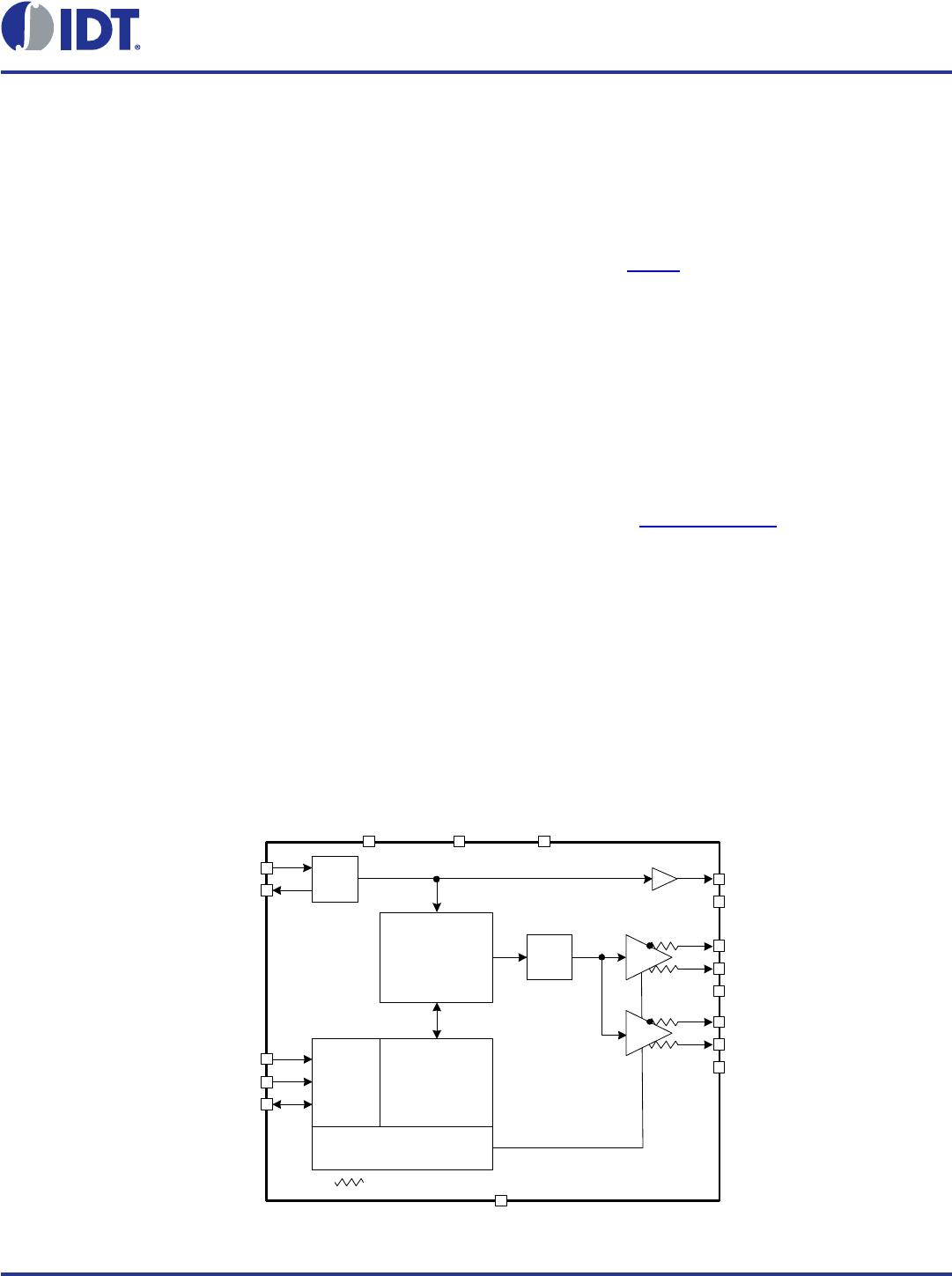
Block Diagram
^SEL1/SDA
Factory
Configuration
SMBus
Engine
INT
PLL
VDDREFp
XO
XIN/CLKIN
VDDDp VDDAp
^SEL0/SCL
OUT0
OUT0#
Control Logic
vSEL_I2C#
EPAD/GND
REF0
Internal terminations are available when LP -HCSL output format is selected.
OSC
OTP_VPP
INT
DIV
OUT1#
OUT1
VDDO1
VDDO0
9FGV1005
Datasheet
Low Phase-Noise, Low-Power
Programmable PhiClock™ Generator
2©2018 Integrated Device Technology, Inc. May 30, 2018
9FGV1005 Datasheet
Pin Assignments
Figure 1. Pin Assignments for 3 x 3 mm 16-LGA Package – Top View
Pin Descriptions
VDDREFp
vREF0_SEL_I2C#
VDDAp
VDDO1
16 15 14 13
XIN/CLKIN 1
12
OUT1
XO 2
11
OUT1#
^SEL0/SCL 3
10
NC
^SEL1/SDA 4
9
VDDO0
5678
VDDDp
OTP_VPP
OUT0#
OUT0
^ prefix indicates internal pull-up resistor
v prefix indicates internal pull-down resistor
9FGV1005
Connect EPAD to
GND
16-LGA 3 x 3 mm, 0.5mm pitch
VDDREFp
vREF0_SEL_I2C#
VDDAp
VDDO1
16 15 14 13
NC 1
12
OUT1
NC 2
11
OUT1#
^SEL0/SCL
3
10
NC
^SEL1/SDA
4
9
VDDO0
5678
VDDDp
OTP_VPP
OUT0#
OUT0
9FGV1005Q
Connect EPAD to
GND
16-LGA 3 x 3 mm, 0.5mm pitch
^ prefix indicates internal pull-up resistor
v prefix indicates internal pull-down resistor
Table 1. Pin Descriptions
Number Name Type Description
1
[a]
XIN/CLKIN Input Crystal input or reference clock input.
2
[a]
XO Output Crystal output.
3
^SEL0/SCL Input
Select pin for internal frequency configurations/I
2
C clock pin. Function is determined
by state of SEL_I2C# upon power-up. This pin has an internal pull-up.
4 ^SEL1/SDA I/O
Select pin for internal frequency configurations/I
2
C data pin. Function is determined by
state of SEL_I2C# upon power-up. This pin has an internal pull-up.
5
V
DDDp
Power
Digital power. 1.8V to 3.3V. V
DDAp
and V
DDDp
should be connected to the same power
supply.
6
OTP_VPP Power
Voltage for programming OTP. During normal operation, this pin should be connected
to the same power rail as V
DDD
.
7 OUT0# Output Complementary output clock 0.
8 OUT0 Output Output clock 0.
9V
DDO0
Power Power supply for output 0.
10 NC No connect.
11 OUT1# Output Complementary output clock 1.
12 OUT1 Output Output clock 1.
13 V
DDO1
Power
Power supply for output 1.
3©2018 Integrated Device Technology, Inc. May 30, 2018
9FGV1005 Datasheet
Note: Unused outputs can be programmed off and left floating. V
DDREF
and V
DDO0
have to be connected.
[a]
These pins are 'No Connect' on 9FGV1005Q integrated quartz versions. See Pin Assignments diagram for 9FGV1005Q.
14 V
DDAp
Power
Power supply for analog circuits. V
DDAp
and V
DDDp
should be connected to the same
power supply. Programmable for nominal voltages of 1.8V, 2.5V or 3.3V.
15 vREF0_SEL_I2C#
Latched
I/O
Latched input/LVCMOS output. At power-up, the state of this pin is latched to select
the state of the I
2
C pins. After power-up, the pin acts as an LVCMOS reference output.
This pin has an internal pull-down.
1 = SEL0/SEL1.
0 = SCL/SDA.
16 V
DDREFp
Power
Power supply for REF0 and REF1 and the internal XO. Programmable to 1.8V, 2.5V or
3.3V.
17 EPAD GND Connect to ground.
Table 1. Pin Descriptions (Cont.)
Number Name Type Description

9FGV1005Q507LTGI

Mfr. #:
Manufacturer:
IDT
Description:
Clock Generators & Support Products 9FGV1005 W/INT 50MHZ XTAL
Lifecycle:
New from this manufacturer.
Delivery:
DHL FedEx Ups TNT EMS
Payment:
T/T Paypal Visa MoneyGram Western Union