AD8494/AD8495/AD8496/AD8497
Rev. C | Page 10 of 16
08529-030
1s/DIV
200nV/DI
V
Figure 21. 0.1 Hz to 10 Hz RTI Voltage Noise
5
4
3
2
1
0
–1
–2
–3
–4
–5
1k 10k 100k
LOAD RESISTANCE ()
OUTPUT VOLTAGE SWING (V)
08529-033
(+) –40°C
(+) +25°C
(+) +85°C
(+) +125°C
(–) –40°C
(–) +25°C
(–) +85°C
(–) +125°C
Figure 22. Output Voltage Swing vs. Load Resistance, V
S
= ±5 V
100
90
80
70
60
50
40
30
20
10
1 10 100 1k 10k 100k
FREQUENCY (Hz)
NOISE (nV/ Hz)
08529-031
Figure 23. Voltage Noise Spectral Density vs. Frequency
08529-032
TIME (1.5ms/DIV)
OUTPUT VOLTAGE
(50mV/DIV)
SUPPLY VOLTAGE
(1.25V/DIV)
OUTPUT VOLTAGE
5V POWER-UP
Figure 24. Output Voltage Start-Up
+
V
S
–0.4
–0.8
–1.2
+1.2
+0.8
+0.4
–V
S
10µ 100µ 1m 5m
OUTPUT CURRENT (A)
OUTPUT VOLTAGE SWING (V)
REFERRED TO SUPPLY VOLTAGES (V
S
= ±5V)
08529-034
(+) –40°C
(+) +25°C
(+) +85°C
(+) +125°C
(–) –40°C
(–) +25°C
(–) +85°C
(–) +125°C
Figure 25. Output Voltage Swing vs. Output Current, V
S
= ±5 V
AD8494/AD8495/AD8496/AD8497
Rev. C | Page 11 of 16
THEORY OF OPERATION
THERMOCOUPLES
A thermocouple is a rugged, low cost temperature transducer
whose output is proportional to the temperature difference
between a measurement junction and a reference junction. It
has a very wide temperature range. Its low level output (typically
tens of microvolts per °C) requires amplification. Variation in
the reference junction temperature results in measurement
error unless the thermocouple signal is properly compensated.
A thermocouple consists of two dissimilar metals. These metals
are connected at one end to form the measurement junction,
also called the hot junction. The other end of the thermocouple
is connected to the metal lines that lead to the measurement
electronics. This connection forms a second junction: the
reference junction, also called the cold junction.
08529-004
AD849x
PCB
TRACES
REFERENCE
JUNCTION
MEASUREMENT
JUNCTION
THERMOCOUPLE WIRES
Figure 26. Thermocouple Junctions
To derive the temperature at the measurement junction (T
MJ
),
the user must know the differential voltage created by the thermo-
couple. The user must also know the error voltage generated by
the temperature at the reference junction (T
RJ
). Compensating
for the reference junction error voltage is typically called cold
junction compensation. The electronics must compensate for
any changes in temperature at the reference (cold) junction so
that the output voltage is an accurate representation of the hot
junction measurement.
THERMOCOUPLE SIGNAL CONDITIONER
The AD8494/AD8495/AD8496/AD8497 thermocouple amplifiers
provide a simple, low cost solution for measuring thermocouple
temperatures. These amplifiers simplify many of the difficulties
of measuring thermocouples. An integrated temperature sensor
performs cold junction compensation. A fixed-gain instrumentation
amplifier amplifies the small thermocouple voltage to provide a
5 mV/°C output. The high common-mode rejection of the
amplifier blocks common-mode noise that the long thermocouple
leads can pick up. For additional protection, the high impedance
inputs of the amplifier make it easy to add extra filtering.
Table 6 shows an example of a J type thermocouple voltage for
various combinations of 0°C and 50°C on the reference and
measurement junctions. Table 6 also shows the performance
of the AD8494 amplifying the thermocouple voltage and
compensating for the reference junction temperature changes,
thus eliminating the error.
Table 6. J Type Thermocouple Voltages and AD8494 Readings
Measurement
Junction
Temperature
(T
MJ
)
Reference
Junction
Temperature
(T
RJ
)
Thermocouple
Voltage
AD8494
Reading
50°C 0°C +2.585 mV 250 mV
50°C 50°C 0 mV 250 mV
0°C 0°C 0 mV 0 mV
0°C 50°C −2.585 mV 0 mV
AD8494/AD8495/AD8496/AD8497 ARCHITECTURE
Figure 27 shows a block diagram of the AD849x circuitry. The
AD849x consists of a low offset, fixed-gain instrumentation
amplifier and a temperature sensor.
–IN
+IN
OUT
REF
08529-020
A1
A2
AD8494/AD8495/
AD8496/AD8497
A3
SENSE
ESD AND
OVP
ESD AND
OVP
COLD JUNCTION
COMPENSATION
1M
THERMO-
COUPLE
Figure 27. Block Diagram
The AD849x output is a voltage that is proportional to the tem-
perature at the measurement junction of the thermocouple (T
MJ
).
To derive the measured temperature from the AD849x output
voltage, use the following transfer function:
T
MJ
= (V
OUT
V
REF
)/(5 mV/°C)
An ideal AD849x achieves this output with an error of less than
±2°C, within the specified operating ranges listed in Table 7 .
Instrumentation Amplifier
A thermocouple signal is so small that considerable gain is
required before it can be sampled properly by most ADCs. The
AD849x has an instrumentation amplifier with a fixed gain that
generates an output voltage of 5 mV/°C for J type and K type
thermocouples.
V
OUT
= (T
MJ
× 5 mV/°C) + V
REF
To accommodate the nonlinear behavior of the thermocouple,
each amplifier has a different gain so that the 5 mV/°C is accu-
rately maintained for a given temperature measurement range.
The AD8494 and AD8496 (J type) have an instrumentation
amplifier with a gain of 96.7 and 90.35, respectively.
The AD8495 and AD8497 (K type) have an instrumentation
amplifier with a gain of 122.4.
AD8494/AD8495/AD8496/AD8497
Rev. C | Page 12 of 16
The small thermocouple voltages mean that signals are quite
vulnerable to interference, especially when measured with
single-ended amplifiers. The AD849x addresses this issue in
several ways. Low input bias currents and high input impedance
allow for easy filtering at the inputs. The excellent common-mode
rejection of the AD849x prevents variations in ground potential
and other common-mode noise from affecting the measurement.
Temperature Sensor (Cold Junction Compensation)
The AD849x also includes a temperature sensor for cold junc-
tion compensation. This temperature sensor is used to measure
the reference junction temperature of the thermocouple and to
cancel its effect.
The AD8494/AD8495 cold junction compensation is
optimized for operation in a lab environment, where the
ambient temperature is around 25°C. The AD8494/AD8495
are specified for an ambient range of 0°C to 50°C.
The AD8496/AD8497 cold junction compensation is
optimized for operation in a less controlled environment,
where the temperature is around 60°C. The AD8496/AD8497
are specified for an ambient range of 25°C to 100°C.
Application examples for the AD8496/AD8497 include
automotive applications, autoclave, and ovens.
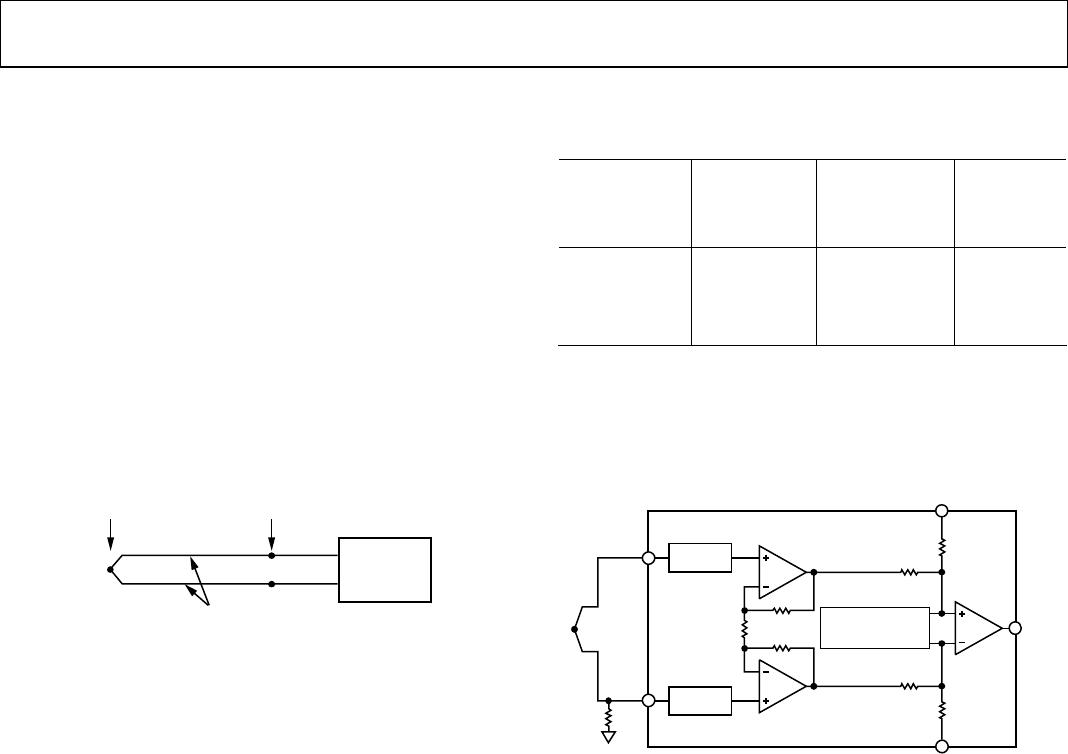
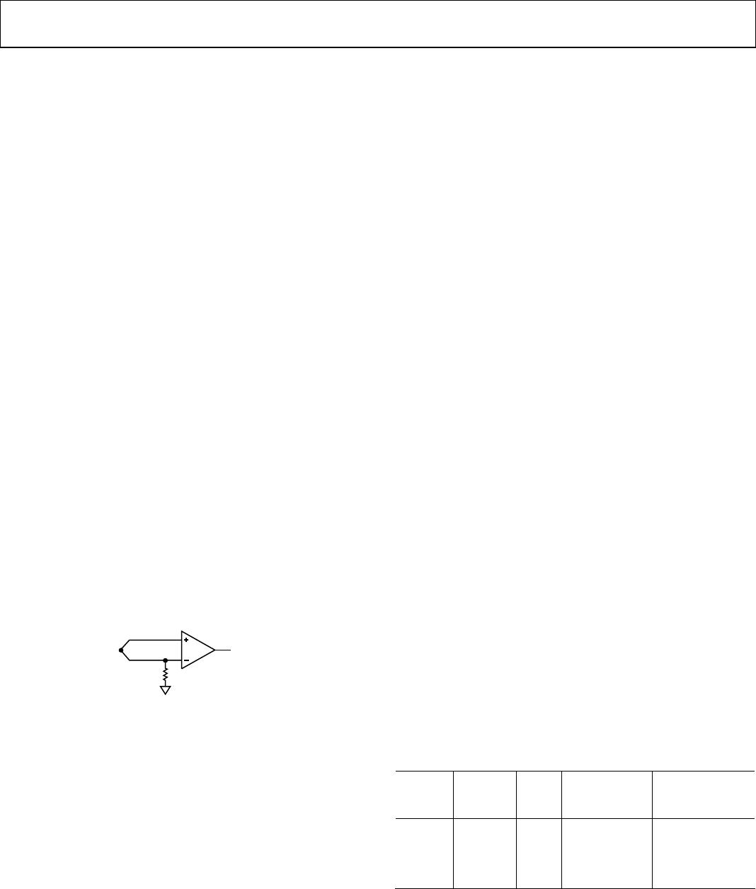
Thermocouple Break Detection
The AD849x offers open thermocouple detection. The inputs
of the AD849x are PNP type transistors, which means that the
bias current always flows out of the inputs. Therefore, the input
bias current drives any unconnected input high, which rails the
output. Connecting the negative input to ground through a
1 MΩ resistor causes the AD849x output to rail high in an open
thermocouple condition (see Figure 6, Figure 28, and the
Ground Connection section).
08529-008
1M
Figure 28. Ground the Negative Input Through a 1 MΩ Resistor
for Open Thermocouple Detection
Input Voltage Protection
The AD849x has very robust inputs. Input voltages can be up
to 25 V from the opposite supply rail. For example, with a +5 V
positive supply and a −3 V negative supply, the part can safely
withstand voltages at the inputs from −20 V to +22 V. Voltages
at the reference and sense pins should not go beyond 0.3 V of
the supply rails.
MAXIMUM ERROR CALCULATION
As is normally the case, the AD849x outputs are subject to
calibration, gain, and temperature sensitivity errors. The user
can calculate the maximum error from the AD849x using the
following information.
The five primary sources of AD849x error are described in this
section.
AD849x Initial Calibration Accuracy
Error at the initial calibration point can be easily calibrated out
with a one-point temperature calibration. See Table 2 for the
specifications.
AD849x Ambient Temperature Rejection
The specified ambient temperature rejection represents the
ability of the AD849x to reject errors caused by changes in the
ambient temperature/reference junction. For example, with
0.025°C/°C ambient temperature rejection, a 20°C change in the
reference junction temperature adds less than 0.5°C error to the
measurement. See Table 2 for the specifications.
AD849x Gain Error
Gain error is the amount of additional error when measuring away
from the measurement junction calibration point. For example,
if the part is calibrated at 25°C and the measurement junction is
100°C with a gain error of 0.1%, the gain error contribution is
(100°C − 25°C) × (0.1%) = 0.075°C. This error can be calibrated
out with a two-point calibration if needed, but it is usually small
enough to ignore. See Tabl e 2 for the specifications.
Manufacturing Tolerances of the Thermocouple
Consult the data sheet for your thermocouple to find the
specified tolerance of the thermocouple.
Linearity Error of the Thermocouple
Each part in the AD849x family is precision trimmed to optimize
a linear operating range for a specific thermocouple type and
for the widest possible measurement and ambient temperature
ranges. The AD849x achieves a linearity error of less than ±2°C,
within the specified operating ranges listed in Table 7. This error
is due only to the nonlinearity of the thermocouple.
Table 7. AD849x ±2°C Accuracy Temperature Ranges
Part
Thermo-
couple
Type
Max
Error
Ambient
Temperature
Range
Measurement
Temperature
Range
AD8494 J ±2°C 0°C to 50°C −35°C to +95°C
AD8495 K ±2°C 0°C to 50°C −25°C to +400°C
AD8496 J ±2°C 25°C to 100°C +55°C to +565°C
AD8497 K ±2°C 25°C to 100°C −25°C to +295°C
For temperature ranges outside those listed in Table 7 or for
instructions on how to correct for thermocouple nonlinearity
error with software, see the AN-1087 Application Note for
additional details.

AD8495CRMZ

Mfr. #:
Manufacturer:
Analog Devices Inc.
Description:
Board Mount Temperature Sensors Thermocouple Amp w/Cold Jct Compensat
Lifecycle:
New from this manufacturer.
Delivery:
DHL FedEx Ups TNT EMS
Payment:
T/T Paypal Visa MoneyGram Western Union