AD8494/AD8495/AD8496/AD8497
Rev. C | Page 13 of 16
Keeping the AD849x at the Same Temperature
as the Reference Junction
RECOMMENDATIONS FOR BEST CIRCUIT
PERFORMANCE
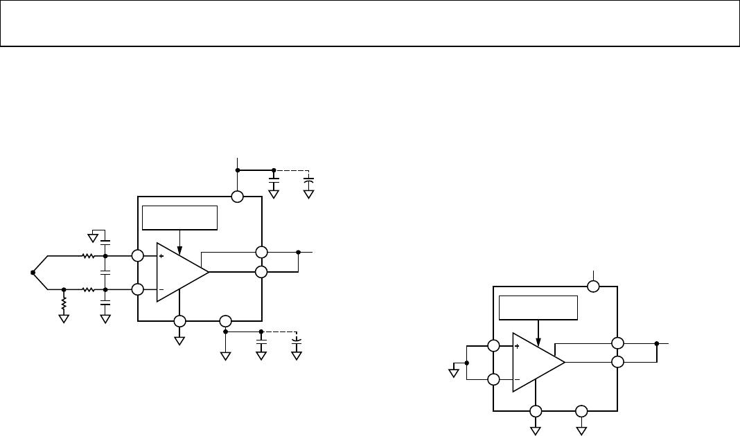
The AD849x compensates for thermocouple reference junction
temperature by using an internal temperature sensor. It is
critical to keep the reference junction (thermocouple-to-PCB
connection) as close to the AD849x as possible. Any difference
in temperature between the AD849x and the reference junction
appears directly as temperature error. Temperature difference
between the device and the reference junction may occur if the
AD849x is not physically close to the reference junction or if the
AD849x is required to supply large amounts of output power.
Input Filter
A low-pass filter before the input of the AD849x is strongly
recommended (see Figure 29), especially when operating in an
electrically noisy environment. Long thermocouple leads can
function as an excellent antenna and pick up many unwanted
signals.
The filter should be set to a low corner frequency that still
allows the input signal to pass through undiminished. The
primary purpose of the filter is to remove RF signals, which,
if allowed to reach the AD849x, can be rectified and appear
as temperature fluctuations.
08529-010
AD849x
PCB
TRACES
KEEP
TRACES
SHORT
KEEP JUNCTION AND
AD849x AT SAME
TEMPERATURE
MEASUREMENT
JUNCTION
REFERENCE
JUNCTION
THERMOCOUPLE WIRES
08529-011
R
R
AD849x
C
D
C
C
C
C
1M
CONNECT WHEN
THERMOCOUPLE TIP
TYPE IS UNKNOWN
FILTER FREQUENCY
DIFF
=
1
2πR(2C
D
+ C
C
)
FILTER FREQUENCY
CM
=
WHERE C
D
10C
C
1
2πRC
C
Figure 31. Compensating for Thermocouple Reference Junction Temperature
Driving the Reference Pin
The AD849x comes with a reference pin, which can be used
to offset the output voltage. This is particularly useful when
reading a negative temperature in a single-supply system.
INCORRECT
V
CORRECT
AD849x
AD8613
+
V
08529-006
REF
AD849x
REF
Figure 29. Filter for Any Thermocouple Style
To prevent input offset currents from affecting the measurement
accuracy, the filter resistor values should be less than 50 k.
Ground Connection
It is always recommended that the thermocouple be connected
to ground through a 100 k to 1 M resistor placed at the
negative (inverting) input of the amplifier on the PCB (see
Figure 30). This solution works well regardless of the thermo-
couple tip style.
08529-038
1M
Figure 32. Driving the Reference Pin
For best performance, the reference pin should be driven with a
low output impedance source, not a resistor divider. The AD8613
and the OP777 are good choices for the buffer amplifier.
Figure 30. Ground the Thermocouple with a 1 MΩ Resistor
Debugging Tip
If there is no electrical connection at the measurement junction
(insulated tip), the resistor value is small enough that no mean-
ingful common-mode voltage is generated. If there is an electrical
connection through a grounded or exposed tip, the resistor value
is large enough that any current from the measurement tip to
ground is very small, preventing measurement errors.
If the AD849x is not providing the expected performance, a
useful debugging step is to implement the ambient temperature
configuration in Figure 34. If the ambient temperature sensor
does not work as expected, the problem is likely with the AD849x
or with the downstream circuitry. If the ambient temperature
sensor configuration is working correctly, the problem typically
lies with how the thermocouple is connected to the AD849x.
Common errors include an incorrect grounding configuration
or lack of filtering.
The AD849x inputs require only one ground connection or source
of common-mode voltage. Any additional ground connection is
detrimental to performance because ground loops can form
through the thermocouple, easily swamping the small
thermocouple signal. Grounding the thermocouple through a
resistor as recommended prevents such problems.
AD8494/AD8495/AD8496/AD8497
Rev. C | Page 14 of 16
APPLICATIONS INFORMATION
BASIC CONNECTION
Figure 33 shows an example of a basic connection for the
AD849x, with a J type or K type thermocouple input.
AD849x
OUT
SENSE
REF
–V
S
+V
S
0.1µF 10µF
5
V
08529-012
COLD JUNCTION
COMPENSATION
2 3
7
5
+IN
THERMO-
COUPLE
–IN
1M
8
1
0.1µF 10µF
6
IN-AMP
Figure 33. Basic Connection for the AD849x
To measure negative temperatures, apply a voltage at the refer-
ence pin to offset the output voltage at 0°C. The output voltage
of the AD849x is
V
OUT
= (T
MJ
× 5 mV/°C) + V
REF
A filter at the input is recommended to remove high frequency
noise. The 1 M resistor to ground enables open thermocouple
detection and proper grounding of the thermocouple. The sense
pin should be connected to the output pin of the AD849x.
Decoupling capacitors should be used to ensure clean power
supply voltages on +V
S
and, if using dual supplies, on −V
S
, also.
A 0.1 µF capacitor should be placed as close as possible to each
AD849x supply pin. A 10 µF tantalum capacitor can be used
farther away from the part and can be shared.
AMBIENT TEMPERATURE SENSOR
The AD849x can be configured as a standalone Celsius thermo-
meter with a 5 mV/°C output, as shown in Figure 34. The
thermocouple sensing functionality is disabled by shorting both
AD849x inputs to ground; the AD849x simply outputs the value
from the on-board temperature sensor.
As a temperature sensor, the AD8494 has a measurement temp-
erature range of −40°C to +125°C with a precision output of
V
OUT
= T
A
× 5 mV/°C
IN-AMP
AD849x
+IN
–IN
OUT
SENSE
REF –V
S
+V
S
5
V
08529-013
COLD JUNCTION
COMPENSATION
8
2 3
5
7
1
6
Figure 34. Ambient Temperature Sensor
The AD8494 is the best choice for use as an ambient temper-
ature sensor. The AD8495, AD8496, and AD8497 can also be
configured as ambient temperature sensors, but their output
transfer functions are not precisely 5 mV/°C. For information
about the exact transfer functions of the AD8494/AD8495/
AD8496/AD8497, see the AN-1087 Application Note for
additional details.
The thermometer mode can be particularly useful for debugging
a misbehaving circuit. If the basic connection is not working,
disconnect the thermocouple and short both inputs to ground.
If the system reads the ambient temperature correctly, the
problem is related to the thermocouple. If the system does not
read the ambient temperature correctly, the problem is with
the AD849x or with the downstream circuitry.
AD8494/AD8495/AD8496/AD8497
Rev. C | Page 15 of 16
SETPOINT CONTROLLER
The AD849x can be used as a temperature setpoint controller,
with a thermocouple input from a remote location or with the
AD849x itself being used as a temperature sensor. When the
measured temperature is below the setpoint temperature, the
output voltage goes to −V
S
. When the measured temperature is
above the setpoint temperature, the output voltage goes to +V
S
.
For best accuracy and CMRR performance, the setpoint voltage
should be created with a low impedance source. If the setpoint
voltage is generated with a voltage divider, a buffer is
recommended.
AD849x
OUT
SENSE
SETPOINT
VOLTAGE
REF
–V
S
+V
S
5
V
08529-014
COLD JUNCTION
COMPENSATION
2 3
7
6
+IN
THERMO-
COUPLE
–IN
1M
8
1
IN-AMP
5
Figure 35. Setpoint Controller
Hysteresis can be added to the setpoint controller by using a
resistor divider from the output to the reference pin, as shown
in Figure 36. The hysteresis in °C is
CmV/5
)/(
°
+×
=
R2R1R1V
T
S
HYST
AD849x
OUT
SENSE
SETPOINT
VOLTAGE
R2
100k
R1
1k
R1
1k
REF
–V
S
+V
S
5V
08529-015
COLD JUNCTION
COMPENSATION
2 3
7
5
+IN
THERMO-
COUPLE
–IN
1M
8
1
IN-AMP
6
Figure 36. Adding 10 Degrees of Hysteresis
A resistor equivalent to the output resistance of the divider should
be connected to the sense pin to ensure good CMRR.
MEASURING NEGATIVE TEMPERATURES
The AD849x can measure negative temperatures on dual
supplies and on a single supply. When operating on dual
supplies with the reference pin grounded, a negative output
voltage indicates a negative temperature at the thermocouple
measurement junction.
V
OUT
= (T
MJ
× 5 mV/°C) + V
REF
When operating the AD849x on a single supply, level-shift
the output by applying a positive voltage (less than +V
S
) on
the reference pin. An output voltage less than V
REF
indicates
a negative temperature at the thermocouple measurement
junction.
REFERENCE PIN ALLOWS OFFSET ADJUSTMENT
The reference pin can be used to level-shift the AD849x output
voltage. This is useful for measuring negative temperatures on a
single supply and to match the AD849x output voltage range to
the input voltage range of the subsequent electronics in the
signal chain.
The reference pin can also be used to offset any initial calibra-
tion errors. Apply a small reference voltage proportional to the
error to nullify the effect of the calibration error on the output.

AD8495CRMZ

Mfr. #:
Manufacturer:
Analog Devices Inc.
Description:
Board Mount Temperature Sensors Thermocouple Amp w/Cold Jct Compensat
Lifecycle:
New from this manufacturer.
Delivery:
DHL FedEx Ups TNT EMS
Payment:
T/T Paypal Visa MoneyGram Western Union