LT8631
19
8631fa
For more information www.linear.com/LT8631
APPLICATIONS INFORMATION
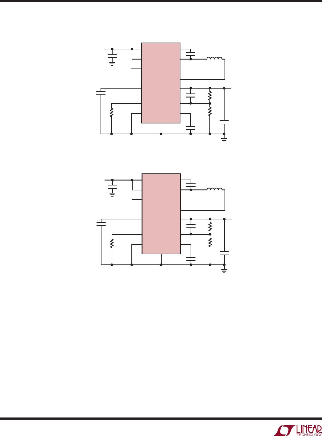
BST
D1
L1
IND
SW
LT8631
GND
8631 F06
C3
Figure 6. External Schottky Catch Diode
Figure 7. LT8631 Efficiency with/without External Schottky
Placing additional vias can reduce thermal resistance
further. The maximum load current should be derated
as the ambient temperature approaches the maximum
junction rating. Power dissipation within the LT8631 can
be estimated by calculating the total power loss from
an efficiency measurement and subtracting the inductor
loss. The die temperature is calculated by multiplying the
LT8631 power dissipation by the thermal resistance from
junction to ambient.
If safe junction temperature is exceeded, the LT8631 will
shutdown and restart with a POR sequence.
External Schottky Catch Diode
For high temperature, high input voltage and high output
load applications, adding a Schottky catch diode (Figure 6),
will lower the LT8631 junction temperature by increasing
efficiency (Figure 7). Use a low leakage Schottky diode
rated greater than 2A with a reverse voltage greater than
the maximum input voltage for the application. A complete
application circuit with the additional Schottky can be found
in the Typical Applications section.
LOAD CURRENT (mA)
0
EFFICIENCY (%)
100
95
90
85
80
50
75
70
65
60
55
300 500 600 700
8631 F07
1000800 900200100 400
T
AMBIENT
= 100°C
F
SW
= 400kHz
V
IN
= 12V WITHOUT SCHOTTKY
V
IN
= 12V WITH SCHOTTKY
V
IN
= 48V WITHOUT SCHOTTKY
V
IN
= 48V WITH SCHOTTKY