ADCMP361YRJZ-REEL7

Data Sheet ADCMP361
SPECIFICATIONS
V
DD
= 1.7 V to 5.5 V, 40°C ≤ T
A
+125°C, unless otherwise noted.
Table 1.
Parameter Min Typ Max Unit Test Conditions/Comments
THRESHOLDS
1
Rising Input Threshold Voltage
400.4
401.5
mV
V
DD
= 3.3 V, T
A
= 25°C
391.2 400.4 407.7 mV V
DD
= 1.7 V
393.1 400.4 405.9 mV V
DD
= 3.3 V
393.1 400.4 405.8 mV V
DD
= 5.5 V
Falling Input Threshold Voltage 381.1 391.1 400.9 mV V
DD
= 1.7 V
391.1
398.4
mV
V
DD
= 3.3 V
381.0 391.1 398.2 mV V
DD
= 5.5 V
Hysteresis = V
TH(R)
V
TH(F)
2 9.3 13.5 mV
Threshold Voltage Accuracy ±0.275 % T
A
= 25°C, V
DD
= 3.3 V
Threshold Voltage Temperature Coefficient 16 ppm/°C
POWER SUPPLY
Supply Current 6.5 9 µA V
DD
= 1.7 V
7.0 10 µA V
DD
= 5.5 V
INPUT CHARACTERISTICS
Input Bias Current 0.01 5 nA V
DD
= 1.7 V, V
IN
= V
DD
0.01 5 nA V
DD
= 1.7 V, V
IN
= 0.1 V
OPEN-DRAIN OUTPUTS
Output Low Voltage
2
140 220 mV V
DD
= 1.7 V, I
OUT
= 3 mA
140 220 mV V
DD
= 5.5 V, I
OUT
= 5 mA
Output Leakage Current
3
0.01
1
µA
V
DD
= 1.7 V, V
OUT
= V
DD
0.01 1 µA V
DD
= 1.7 V, V
OUT
= 5.5 V
DYNAMIC PERFORMANCE
High-to-Low Propagation Delay
2, 4
10
µs
V
DD
= 5 V, V
OL
= 400 mV
Low-to-High Propagation Delay
2, 4
8 µs V
DD
= 5 V, V
OH
= 0.9 × V
DD
Output Rise time
2, 4
0.5 µs V
DD
= 5 V, V
O
= (0.1 to 0.9) × V
DD
Output Fall time
2, 4
0.07 µs V
DD
= 5 V, V
O
= (0.1 to 0.9) × V
DD
1
R
L
= 100 kΩ, V
O
= 2 V swing.
2
10 mV input overdrive.
3
V
IN
= 40 mV overdrive.
4
R
L
= 10 kΩ.
Rev. B | Page 3 of 12
ADCMP361 Data Sheet
Rev. B | Page 4 of 12
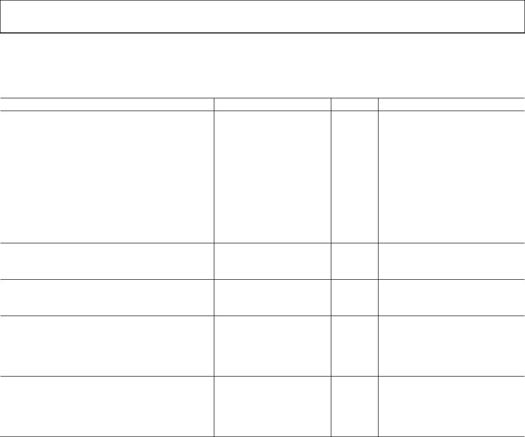
ABSOLUTE MAXIMUM RATINGS
Table 2.
Parameter Rating
V
DD
−0.3 V to +6 V
IN −0.3 V to +6 V
OUT, OUT
−0.3 V to +6 V
Operating Temperature Range −40°C to +125°C
Storage Temperature Range −65°C to +150°C
Lead Temperature
Soldering (10 sec) 300°C
Vapor Phase (60 sec) 215°C
Infrared (15 sec) 220°C
Stresses above those listed under Absolute Maximum Ratings
may cause permanent damage to the device. This is a stress
rating only; functional operation of the device at these or any
other conditions above those indicated in the operational
section of this specification is not implied. Exposure to absolute
maximum rating conditions for extended periods may affect
device reliability.
THERMAL CHARACTERISTICS
θ
JA
is specified for the worst-case conditions, that is, a device
soldered in a circuit board for surface-mount packages.
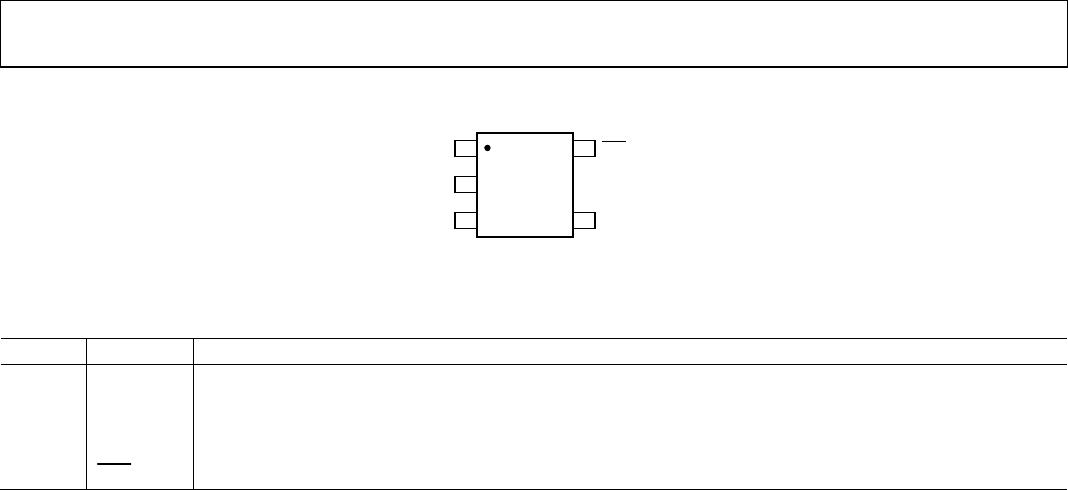
Table 3. Thermal Resistance
Package Type θ
JA
Unit
5-Lead SOT-23 240 °C/W
ESD CAUTION
Data Sheet ADCMP361
Rev. B | Page 5 of 12
PIN CONFIGURATION AND FUNCTION DESCRIPTIONS
1
OUT
5
OUT
2
GND
3
IN
4
V
DD
ADCMP361
TOP VIEW
(Not to Scale)
06496-002
Figure 4. Pin Configuration
Table 4. Pin Function Descriptions
Pin No. Mnemonic Description
1 OUT Noninverting Open-Drain Output.
2 GND Ground.
3 IN Monitors analog input voltage on comparator. The other input of the comparator is connected to a 400 mV reference.
4 V
DD
Power Supply.
5
OUT
Inverting Open-Drain Output.

ADCMP361YRJZ-REEL7

Mfr. #:
Manufacturer:
Analog Devices Inc.
Description:
Analog Comparators SGL 0.275% Ref w/ Dual Polarity Output
Lifecycle:
New from this manufacturer.
Delivery:
DHL FedEx Ups TNT EMS
Payment:
T/T Paypal Visa MoneyGram Western Union

Products related to this Datasheet