Expand menu
0
Cart
Home
Products
Sensors
Semiconductors
Passive Components
Connectors
Power
Electromechanical
Optoelectronics
Circuit Protection
Integrated Circuits - ICs
Main Products
Manufacturers
Blog
Services
About OMO
About Us
Contact Us
Check Stock
ADCMP361YRJZ-REEL7
P1-P3
P4-P6
P7-P9
P10-P12
P13-P13
ADCMP36
1
Data Sheet
TYPICAL PE
RFORMANCE
CHARACTE
RISTICS
0
10
20
30
40
50
PERCENT
O
F UNI
TS
(%)
RIS
ING INP
UT TH
RES
HOLD
VOLTAGE
(mV
)
60
394
395
396
397
398
399
400
401
402
403
404
405
406
06496-003
V
DD
= 5V
T
A
= 25°
C
Figure
5
. Distr
ibution of R
ising Input
Threshold Voltage
0
5
10
15
20
25
30
PERCENT
O
F UNI
TS
(%)
HYSTERESIS (mV)
35
6.0
6.4
6.8
7.2
7.6
8.0
8.4
8.8
9.2
9.6
10.0
10.4
10.8
06496-004
V
DD
= 5V
T
A
= 25°
C
Figure
6
. Distribution
of Hysteresis
395
RIS
ING INP
UT TH
RES
HOLD
VOLTAGE
(mV
)
SUPPLY VOLT
AGE (V)
401
400
399
398
397
396
1.7
5.7
5.2
4.7
4.2
3.7
3.2
2.7
2.2
T
A
= –40°
C
T
A
= +25°
C
T
A
= +85°
C
T
A
= +125°
C
06496-007
Figure
7.
Rising Input Threshold Voltage vs. Supply Voltage
0
10
20
30
40
PERCENT
O
F UNI
TS
(%)
FALLIN
G INPU
T THR
ESH
OLD V
OLTAGE (
mV)
50
388
389
390
391
392
393
394
395
396
397
398
399
400
06496-006
V
DD
= 5V
T
A
= 25°
C
Figure
8
. Distribut
ion of Fal
ling Input Threshold Voltage
396
RIS
ING INP
UT TH
RES
HOLD
VOLTAGE
(mV
)
TEMPERATURE (°C)
404
402
400
398
–40
–20
120
0
20
40
60
80
100
4
3
2
1
06496-005
FO
UR TY
PICAL
PART
S
V
DD
= 5V
Figure
9.
Rising Input Threshold Voltage vs. T
emperature
4.0
4.5
5.0
5.5
6.0
6.5
7.0
7.5
8.0
8.5
9.0
9.5
10.0
10.5
11.0
11.5
HYSTERESIS (mV)
TEMPERATURE (°C)
12.0
–40
–20
120
0
20
40
60
80
100
06496-010
V
DD
= 5.0V
V
DD
= 3.3V
V
DD
= 2.5V
V
DD
= 1.8V
Figure
10
.
Hysteresis vs
. T
emperature
Rev.
B
| Page
6
of
12
Data Sheet
ADCM
P361
4
5
6
7
8
9
10
11
HYSTERESIS (mV)
SUPPLY VOLT
AGE (V)
12
1.7
5.7
5.2
4.7
4.2
3.7
3.2
2.7
2.2
T
A
= +125°
C
T
A
= +25°
C
T
A
= +85°
C
T
A
= –40°
C
06496-008
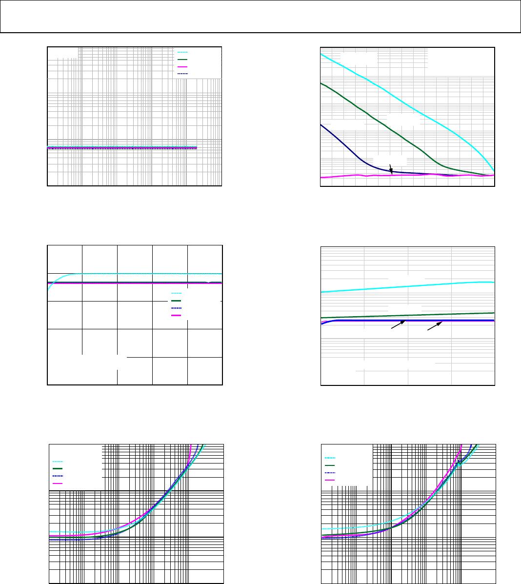
Figure
11
.
Hysteresis vs
. Supply V
oltage
10
4
5.2
SUPPL
Y CURRE
NT (mA)
SUPPLY VOLT
AGE (V)
9
8
7
6
5
1.7
2.
2
2.7
3.
2
3.7
4.2
4.
7
T
A
= +125°
C
T
A
= +85°
C
T
A
= +25°
C
T
A
= –40°
C
06496-009
NO L
OAD CURRE
NT
Figure
12
.
Quiescent Supply Current vs. Supply Voltage
1
SUPPL
Y CURRE
NT (µ
A)
OUT
PUT
SINK CURRE
NT (
mA)
1000
100
10
0.001
100
10
1
0.1
0.01
T
A
= –40°
C
V
DD
= 5.0V
V
DD
= 3.3V
V
DD
= 2.5V
V
DD
= 1.7V
06496-013
Figure
13
.
Supply Current vs. Output Sink Current
–5
THRES
HOL
D SHI
FT
(mV)
SUPPLY VOLT
AGE (V)
1
1.5
2.5
2.4
2.
3
2.2
2.1
2.0
1.
9
1.8
1.
7
1.6
06496-011
T
A
= +125°
C
T
A
= +85°
C
T
A
= +25°
C
T
A
= –40°
C
0
–1
–2
–3
–4
Figure
14
.
Minimum Su
pply Voltage
50
0
1.5
SUPPL
Y CURRE
NT (µ
A)
SUPPLY VOLT
AGE (V)
40
30
20
10
0
0.5
1.0
06496-012
T
A
= +125°
C
T
A
= +85°
C
T
A
= +25°
C
T
A
= –40°
C
Figure
15
.
Start-
Up
Su
pply Current
1
SUPPL
Y CURRE
NT (µ
A)
OUT
PUT
SINK CURRE
NT (
mA)
1000
100
10
0.001
100
10
1
0.1
0.01
V
DD
= 5.0V
V
DD
= 3.3V
V
DD
= 2.5V
V
DD
= 1.7V
T
A
= 25°
C
06496-014
Figure
16
.
Supply C
urrent vs.
O
utput Sink Current
Rev.
B
| Page
7
of
12
ADCMP36
1
Data Sheet
1
SUPPL
Y CURRE
NT (µ
A)
OUT
PUT
SINK CURRE
NT (
mA)
1000
100
10
0.001
100
10
1
0.1
0.01
V
DD
= 5.0V
V
DD
= 3.3V
V
DD
= 2.5V
V
DD
= 1.7V
T
A
= 85°
C
06496-015
Figure
17
.
Supply Current vs. Output Sink Current
–7
1.0
INPUT
BI
AS CURRENT
(n
A)
INP
UT VOLTA
GE (V)
–3
–5
0
0.2
0.6
–1
3
1
0.4
0.8
T
A
= +125°
C
T
A
= +85°
C
T
A
= +25°
C
T
A
= –40°
C
06496-017
CU
RR
ENT IS
POSITIVE
GOING IN
TO THE D
EVIC
E.
V
DD
= 5V
0V < V
IB
< 1V
Figure
18
.
Lo
w Level Input Bias C
urren
t
1
OUTP
UT SA
TUR
ATION
VOLTAGE
(mV
)
OUT
PUT
SINK CURRE
NT (
mA)
100
10
0.001
0.1
0.01
1000
10
1
V
DD
= 5.0V
V
DD
= 3.3V
V
DD
= 2.5V
V
DD
= 1.8V
06496-019
T
A
= 25°
C
Figure
19
.
Output Saturation Voltage vs. Output Sink Current
0.1
0
INPUT
BI
AS CURRENT
(n
A)
INP
UT VOLTA
GE (V)
1k
10k
100
10
1
–0.3
–0.2
–0.1
T
A
= +125°
C
T
A
= +85°
C
T
A
= +25°
C
T
A
= –40°
C
06496-016
CURRENT I
S G
OI
NG
OUT OF TH
E DE
VICE
.
V
DD
= 5V
–0.3V <
V
IB
< 0V
Figure
20
.
Below Ground Input Bias Current
0.01
5
INPUT
BI
AS CURRENT
(n
A)
INP
UT VOLTA
GE (V)
1
0.1
1
2
4
10
3
T
A
= –40°
C
06496-018
T
A
= +125°
C
T
A
= +85°
C
T
A
= +25°
C
CU
RR
ENT IS
GOING IN
TO THE D
EVIC
E
V
DD
= 5V
V
IB
> 1V
Figure
21
.
High Lev
el Input Bias Current
1
OUTP
UT SA
TUR
ATION
VOLTAGE
(mV
)
OUT
PUT
SINK CURRE
NT (
mA)
100
10
0.001
0.1
1000
10
0.01
1
V
DD
= 5.0V
T
A
= –40°
C
V
DD
= 3.3V
V
DD
= 2.5V
V
DD
= 1.8V
06496-020
Figure
22
. Output
Saturation
Voltage vs.
Output Sink Current
Rev.
B
| Page
8
of
12
P1-P3
P4-P6
P7-P9
P10-P12
P13-P13
ADCMP361YRJZ-REEL7
Mfr. #:
Buy ADCMP361YRJZ-REEL7
Manufacturer:
Analog Devices Inc.
Description:
Analog Comparators SGL 0.275% Ref w/ Dual Polarity Output
Lifecycle:
New from this manufacturer.
Delivery:
DHL
FedEx
Ups
TNT
EMS
Payment:
T/T
Paypal
Visa
MoneyGram
Western
Union
Products related to this Datasheet
ADCMP361YRJZ-REEL7
ADCMP361WYRJZ-RL7