Data Sheet AD5246
Rev. C | Page 15 of 16
LAYOUT AND POWER SUPPLY BYPASSING
It is a good practice to use a compact, minimum lead-length
layout design. The leads to the inputs should be as direct as
possible with a minimum conductor length. Ground paths
should have low resistance and low inductance.
Similarly, it is good practice to bypass the power supplies with
quality capacitors for optimum stability. Supply leads to the
device should be bypassed with 0.01 µF to 0.1 µF disc or chip
ceramic capacitors. Low ESR 1 µF to 10 µF tantalum or
electrolytic capacitors should also be applied at the supplies to
minimize any transient disturbance and low frequency ripple
(see Figure 34). Note that the digital ground should also be
joined remotely to the analog ground at one point to minimize
the ground bounce.
AD5246
V
DD
C1
C3
GND
10µF
0.1µF
+
V
DD
03875-017
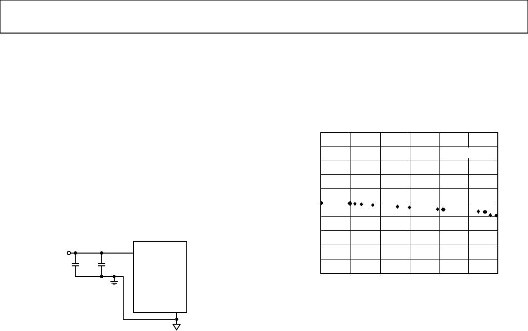
Figure 34. Power Supply Bypassing
CONSTANT BIAS TO RETAIN RESISTANCE SETTING
For users who desire nonvolatility but cannot justify the addi-
tional cost for the EEMEM, the AD5246 may be considered as
a low cost alternative by maintaining a constant bias to retain
the wiper setting. The AD5246 was designed specifically with
low power in mind, which allows low power consumption
even in battery-operated systems. The graph in Figure 35
demonstrates the power consumption from a 3.4 V 450 mA/hr
Li-ion cell phone battery, which is connected to the AD5246.
The measurement over time shows that the device draws
approximately 1.3 µA and consumes negligible power. Over
a course of 30 days, the battery was depleted by less than 2%,
the majority of which is due to the intrinsic leakage current
of the battery itself.
DAYS
BATTERY LIFE DEPLETED
0
90%
92%
94%
96%
5 10 15
98%
100%
102%
104%
106%
108%
110%
20 25 30
T
A
= 25°
C
03875-035
Figure 35. Battery Operating Life Depletion
This demonstrates that constantly biasing the pot is not an
impractical approach. Most portable devices do not require the
removal of batteries for the purpose of charging. Although the
resistance setting of the AD5246 will be lost when the battery
needs replacement, such events occur rather infrequently, so
that this inconvenience is justified by the lower cost and smaller
size offered by the AD5246. If and when total power is lost,
the user should be provided with a means to adjust the setting
accordingly.