1
LTC4054-4.2/LTC4054X-4.2
405442xf
FEATURES
DESCRIPTIO
U
APPLICATIO S
U
TYPICAL APPLICATIO
U
Standalone Linear
Li-Ion Battery Charger with
Thermal Regulation in ThinSOT
, LTC and LT are registered trademarks of Linear Technology Corporation.
Programmable Charge Current Up to 800mA
No MOSFET, Sense Resistor or Blocking
Diode Required
Complete Linear Charger in ThinSOT
TM
Package for
Single Cell Lithium-Ion Batteries
Constant-Current/Constant-Voltage Operation with
Thermal Regulation* to Maximize Charge Rate
Without Risk of Overheating
Charges Single Cell Li-Ion Batteries Directly
from USB Port
Preset 4.2V Charge Voltage with ±1% Accuracy
Charge Current Monitor Output for Gas
Gauging*
Automatic Recharge
Charge Status Output Pin
C/10 Charge Termination
25µA Supply Current in Shutdown
2.9V Trickle Charge Threshold (LTC4054)
Available Without Trickle Charge (LTC4054X)
Soft-Start Limits Inrush Current
Available in 5-Lead SOT-23 Package
Cellular Telephones, PDAs, MP3 Players
Charging Docks and Cradles
Bluetooth Applications
ThinSOT is a trademark of Linear Technology Corporation.
*U.S.Patent No. 6,522,118
The LTC
®
4054 is a complete constant-current/constant-
voltage linear charger for single cell lithium-ion batteries.
Its ThinSOT package and low external component count
make the LTC4054 ideally suited for portable applications.
Furthermore, the LTC4054 is specifically designed to work
within USB power specifications.
No external sense resistor is needed, and no blocking
diode is required due to the internal MOSFET architecture.
Thermal feedback regulates the charge current to limit the
die temperature during high power operation or high
ambient temperature. The charge voltage is fixed at 4.2V,
and the charge current can be programmed externally with
a single resistor. The LTC4054 automatically terminates
the charge cycle when the charge current drops to 1/10th
the programmed value after the final float voltage is
reached.
When the input supply (wall adapter or USB supply) is
removed, the LTC4054 automatically enters a low current
state, dropping the battery drain current to less than 2µA.
The LTC4054 can be put into shutdown mode, reducing
the supply current to 25µA.
Other features include charge current monitor, undervoltage
lockout, automatic recharge and a status pin to indicate
charge termination and the presence of an input voltage.
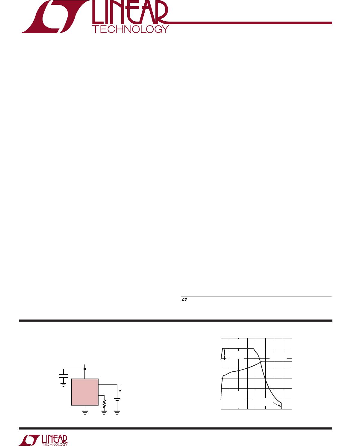
600mA Single Cell Li-Ion Charger
V
CC
1.65k
4.2V
Li-Ion
BATTERY
405442 TA01a
LTC4054-4.2
1µF
V
IN
4.5V TO 6.5V
BAT
4
3
5
2
PROG
GND
600mA
Complete Charge Cycle (750mAh Battery)
TIME (HOURS)
0
CHARGE CURRENT (mA)
1.5
405442 TAO1b
0.5 1.0 2.0
700
600
500
400
300
200
100
0
4.75
4.50
4.25
4.00
3.75
3.50
3.25
3.00
0.25 0.75 1.25 1.75
CONSTANT
POWER
CONSTANT
VOLTAGE
CONSTANT
CURRENT
CHARGE
TERMINATED
BATTERY VOLTAGE (V)
V
CC
= 5V
θ
JA
= 130°C/W
R
PROG
= 1.65k
T
A
= 25°C
2
LTC4054-4.2/LTC4054X-4.2
405442xf
(Note 1)
Input Supply Voltage (V
CC
) ....................... –0.3V to 10V
PROG.............................................0.3V to V
CC
+ 0.3V
BAT..............................................................0.3V to 7V
CHRG........................................................0.3V to 10V
BAT Short-Circuit Duration .......................... Continuous
BAT Pin Current ................................................. 800mA
PROG Pin Current................................................ 800µA
Maximum Junction Temperature .......................... 125°C
Operating Ambient Temperature Range
(Note 2) .............................................. 40°C to 85°C
Storage Temperature Range ................. 65°C to 125°C
Lead Temperature (Soldering, 10 sec).................. 300°C
T
JMAX
= 125°C,
JA
= 80°C/ W TO
150°C/W DEPENDING ON PC BOARD LAYOUT)
(N0TE 3)
ORDER PART
NUMBER
S5 PART MARKING
LTH7
LTADY
SYMBOL PARAMETER CONDITIONS MIN TYP MAX UNITS
V
CC
Input Supply Voltage 4.25 6.5 V
I
CC
Input Supply Current Charge Mode (Note 4), R
PROG
= 10k 300 2000 µA
Standby Mode (Charge Terminated)
200 500 µA
Shutdown Mode (R
PROG
Not Connected, 25 50 µA
V
CC
< V
BAT
, or V
CC
< V
UV
)
V
FLOAT
Regulated Output (Float) Voltage 0°C T
A
85°C, I
BAT
= 40mA 4.158 4.2 4.242 V
I
BAT
BAT Pin Current R
PROG
= 10k, Current Mode 93 100 107 mA
R
PROG
= 2k, Current Mode 465 500 535 mA
Standby Mode, V
BAT
= 4.2V 0 –2.5 –6 µA
Shutdown Mode (R
PROG
Not Connected) ±1 ±2 µA
Sleep Mode, V
CC
= 0V ±1 ±2 µA
I
TRIKL
Trickle Charge Current V
BAT
< V
TRIKL
, R
PROG
= 2k (Note 5) 20 45 70 mA
V
TRIKL
Trickle Charge Threshold Voltage R
PROG
= 10k, V
BAT
Rising (Note 5) 2.8 2.9 3.0 V
V
TRHYS
Trickle Charge Hysteresis Voltage R
PROG
= 10k (Note 5) 60 80 110 mV
V
UV
V
CC
Undervoltage Lockout Threshold From V
CC
Low to High 3.7 3.8 3.92 V
V
UVHYS
V
CC
Undervoltage Lockout Hysteresis 150 200 300 mV
V
MSD
Manual Shutdown Threshold Voltage PROG Pin Rising 1.15 1.21 1.30 V
PROG Pin Falling
0.9 1.0 1.1 V
V
ASD
V
CC
– V
BAT
Lockout Threshold Voltage V
CC
from Low to High 70 100 140 mV
V
CC
from High to Low 5 30 50 mV
I
TERM
C/10 Termination Current Threshold R
PROG
= 10k (Note 6) 0.085 0.10 0.115 mA/mA
R
PROG
= 2k 0.085 0.10 0.115 mA/mA
V
PROG
PROG Pin Voltage R
PROG
= 10k, Current Mode 0.93 1.0 1.07 V
I
CHRG
CHRG Pin Weak Pull-Down Current V
CHRG
= 5V 8 20 35 µA
V
CHRG
CHRG Pin Output Low Voltage I
CHRG
= 5mA 0.35 0.6 V
V
RECHRG
Recharge Battery Threshold Voltage V
FLOAT
- V
RECHRG
100 150 200 mV
The denotes specifications which apply over the full operating
temperature range, otherwise specifications are at T
A
= 25°C. V
CC
= 5V, unless otherwise noted.
ABSOLUTE AXI U RATI GS
WWWU
PACKAGE/ORDER I FOR ATIO
UU
W
ELECTRICAL CHARACTERISTICS
Consult LTC Marketing for parts specified with wider operating temperature ranges.
CHRG 1
GND 2
TOP VIEW
S5 PACKAGE
5-LEAD PLASTIC TSOT-23
BAT 3
5 PROG
4 V
CC
LTC4054ES5-4.2
LTC4054XES5-4.2
3
LTC4054-4.2/LTC4054X-4.2
405442xf
Note 1: Absolute Maximum Ratings are those values beyond which the life
of the device may be impaired.
Note 2: The LTC4054E-4.2 and the LTC4054XE-4.2 are guaranteed to meet
performance specifications from 0°C to 70°C. Specifications over the
–40°C to 85°C operating temperature range are assured by design,
characterization and correlation with statistical process controls.
Note 3: See Thermal Considerations.
SYMBOL PARAMETER CONDITIONS MIN TYP MAX UNITS
T
LIM
Junction Temperature in Constant 120 °C
Temperature Mode
R
ON
Power FET “ON” Resistance 600 m
(Between V
CC
and BAT)
t
SS
Soft-Start Time I
BAT
= 0 to I
BAT
=1000V/R
PROG
100 µs
t
RECHARGE
Recharge Comparator Filter Time V
BAT
High to Low 0.75 2 4.5 ms
t
TERM
Termination Comparator Filter Time I
BAT
Falling Below I
CHG
/10 400 1000 2500 µs
I
PROG
PROG Pin Pull-Up Current 3 µA
The denotes specifications which apply over the full operating
temperature range, otherwise specifications are at T
A
= 25°C. V
CC
= 5V, unless otherwise noted.
ELECTRICAL CHARACTERISTICS
Note 4: Supply current includes PROG pin current (approximately 100µA)
but does not include any current delivered to the battery through the BAT
pin (approximately 100mA).
Note 5: This parameter is not applicable to the LTC4054X.
Note 6: I
TERM
is expressed as a fraction of measured full charge current
with indicated PROG resistor.
TYPICAL PERFOR A CE CHARACTERISTICS
UW
PROG Pin Voltage vs Supply
Voltage(Constant Current Mode)
PROG Pin Voltage vs
Temperature
Charge Current vs
PROG Pin Voltage
V
PROG
(V)
V
CC
(V)
4.0
V
PROG
(V)
1.015
1.010
1.005
1.000
0.995
0.990
0.985
4.5
5.0 5.5 6.0
4054 G01
6.5 7.0
TEMPERATURE (°C)
50 25 0 5025
75
100
4054 G02
1.0100
1.0075
1.0050
1.0025
1.0000
0.9975
0.9950
0.9925
0.9900
V
PROG
(V)
0
I
BAT
(mA)
600
500
400
300
200
100
0
0.25 0.50 0.75 1.00
4054 G03
1.25
V
CC
= 5V
V
BAT
= 4V
T
A
= 25°C
R
PROG
= 10k
V
CC
= 5V
V
BAT
= 4V
R
PROG
= 10k
V
CC
= 5V
T
A
= 25°C
R
PROG
= 2k

LTC4054ES5-4.2#TRPBF

Mfr. #:
Manufacturer:
Analog Devices / Linear Technology
Description:
Battery Management Monolithis Li-Ion Battery Charger
Lifecycle:
New from this manufacturer.
Delivery:
DHL FedEx Ups TNT EMS
Payment:
T/T Paypal Visa MoneyGram Western Union