10
LTC4054-4.2/LTC4054X-4.2
405442xf
APPLICATIO S I FOR ATIO
WUUU
Stability Considerations
The constant-voltage mode feedback loop is stable with-
out an output capacitor provided a battery is connected to
the charger output. With no battery present, an output
capacitor is recommended to reduce ripple voltage. When
using high value, low ESR ceramic capacitors, it is recom-
mended to add a 1 resistor in series with the capacitor.
No series resistor is needed if tantalum capacitors are
used.
In constant-current mode, the PROG pin is in the feedback
loop, not the battery. The constant-current mode stability
is affected by the impedance at the PROG pin. With no
additional capacitance on the PROG pin, the charger is
stable with program resistor values as high as 20k. How-
ever, additional capacitance on this node reduces the
maximum allowed program resistor. The pole frequency
at the PROG pin should be kept above 100kHz. Therefore,
if the PROG pin is loaded with a capacitance, C
PROG
, the
following equation can be used to calculate the maximum
resistance value for R
PROG
:
R
C
PROG
PROG
π
1
210
5
••
Average, rather than instantaneous, charge current may
be of interest to the user. For example, if a switching power
supply operating in low current mode is connected in
parallel with the battery, the average current being pulled
out of the BAT pin is typically of more interest than the
instantaneous current pulses. In such a case, a simple RC
filter can be used on the PROG pin to measure the average
battery current as shown in Figure 2. A 10k resistor has
been added between the PROG pin and the filter capacitor
to ensure stability.
Power Dissipation
The conditions that cause the LTC4054 to reduce charge
current through thermal feedback can be approximated by
considering the power dissipated in the IC. Nearly all of
this power dissipation is generated by the internal
MOSFET—this is calculated to be approximately:
P
D
= (V
CC
– V
BAT
) • I
BAT
where P
D
is the power dissipated, V
CC
is the input supply
voltage, V
BAT
is the battery voltage and I
BAT
is the charge
current. The approximate ambient temperature at which
the thermal feedback begins to protect the IC is:
T
A
= 120°C – P
D
θ
JA
T
A
= 120°C – (V
CC
– V
BAT
) • I
BAT
θ
JA
Example: An LTC4054 operating from a 5V USB supply is
programmed to supply 400mA full-scale current to a
discharged Li-Ion battery with a voltage of 3.75V. Assum-
ing θ
JA
is 150°C/W (see Board Layout Considerations), the
ambient temperature at which the LTC4054 will begin to
reduce the charge current is approximately:
T
A
= 120°C – (5V – 3.75V) • (400mA) • 150°C/W
T
A
= 120°C – 0.5W • 150°C/W = 120°C – 75°C
T
A
= 45°C
PROG
10k
R
PROG
C
FILTER
405442 F02
CHARGE
CURRENT
MONITOR
CIRCUITRY
LTC4054
GND
Figure 2. Isolating Capacitive Load on PROG Pin and Filtering
11
LTC4054-4.2/LTC4054X-4.2
405442xf
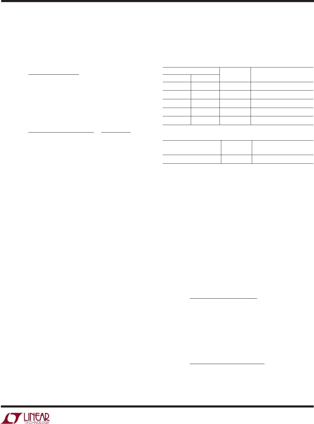
The following table lists thermal resistance for several
different board sizes and copper areas. All measurements
were taken in still air on 3/32" FR-4 board with the device
mounted on topside.
Table 1. Measured Thermal Resistance (2-Layer Board*)
COPPER AREA BOARD THERMAL RESISTANCE
TOPSIDE BACKSIDE AREA JUNCTION-TO-AMBIENT
2500mm
2
2500mm
2
2500mm
2
125°C/W
1000mm
2
2500mm
2
2500mm
2
125°C/W
225mm
2
2500mm
2
2500mm
2
130°C/W
100mm
2
2500mm
2
2500mm
2
135°C/W
50mm
2
2500mm
2
2500mm
2
150°C/W
Table 2. Measured Thermal Resistance (4-Layer Board**)
COPPER AREA BOARD THERMAL RESISTANCE
(EACH SIDE) AREA JUNCTION-TO-AMBIENT
2500mm
2***
2500mm
2
80°C/W
Increasing Thermal Regulation Current
Reducing the voltage drop across the internal MOSFET
can significantly decrease the power dissipation in the IC.
This has the effect of increasing the current delivered to
the battery during thermal regulation. One method is by
dissipating some of the power through an external compo-
nent, such as a resistor or diode.
Example: An LTC4054 operating from a 5V wall adapter is
programmed to supply 800mA full-scale current to a
discharged Li-Ion battery with a voltage of 3.75V. Assum-
ing θ
JA
is 125°C/W, the approximate charge current at an
ambient temperature of 25°C is:
I
CC
VVCW
mA
BAT
=
°°
°
=
120 25
5 3 75 125
608
(–. ) /
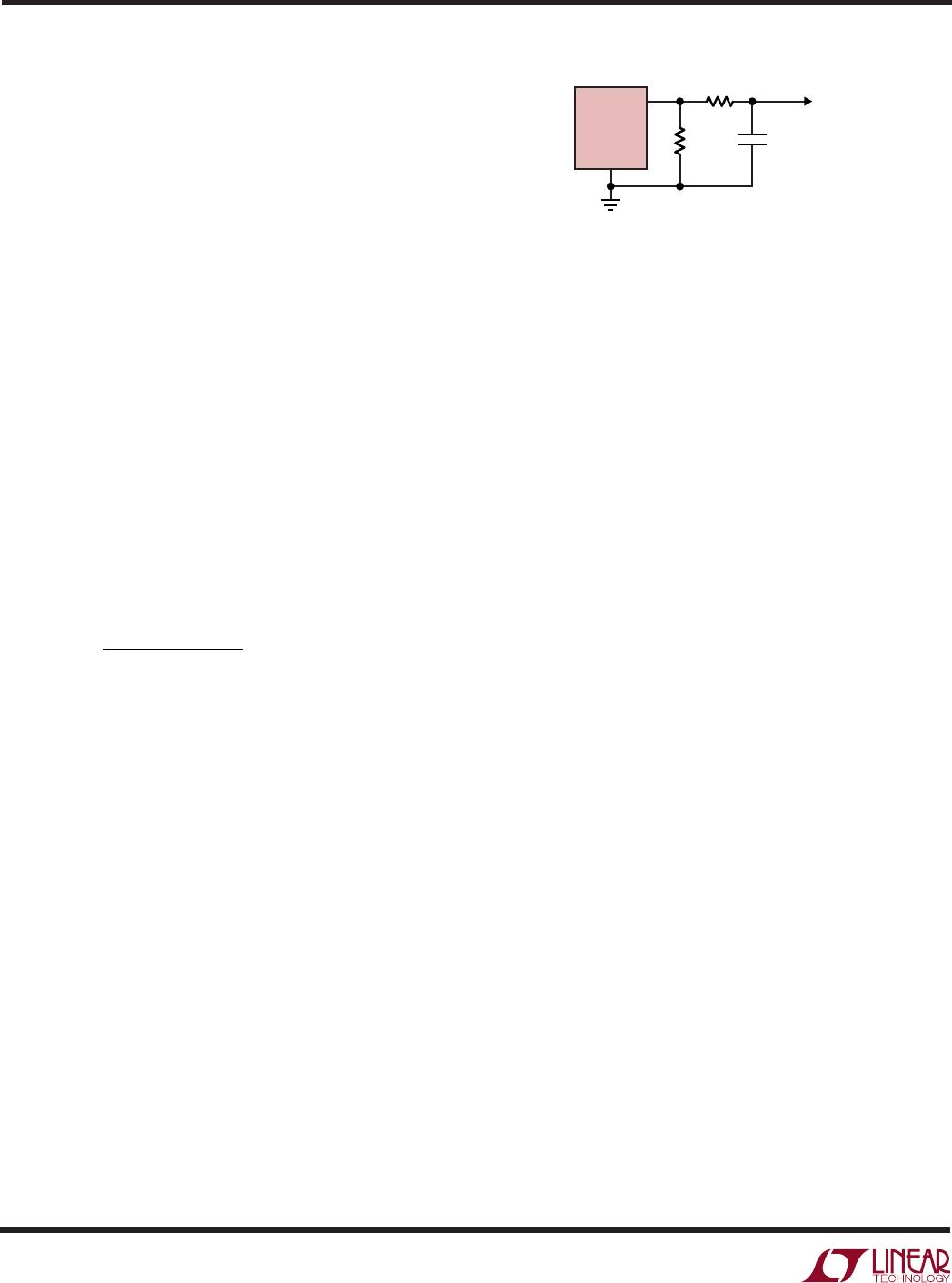
By dropping voltage across a resistor in series with a 5V
wall adapter (shown in Figure 3), the on-chip power
dissipation can be decreased, thus increasing the ther-
mally regulated charge current
I
CC
VIR V
BAT
S BAT CC BAT JA
=
°°120 25
(– )θ
APPLICATIO S I FOR ATIO
WUUU
The LTC4054 can be used above 45°C ambient, but the
charge current will be reduced from 400mA. The approxi-
mate current at a given ambient temperature can be
approximated by:
I
CT
VV
BAT
A
CC BAT JA
=
°
()
120
–•θ
Using the previous example with an ambient temperature
of 60°C, the charge current will be reduced to approxi-
mately:
I
CC
VV CW
C
CA
ImA
BAT
BAT
=
°°
()
°
=
°
°
=
120 60
5 3 75 150
60
187 5
320
–. /
./
Moreover, when thermal feedback reduces the charge
current, the voltage at the PROG pin is also reduced
proportionally as discussed in the Operation section.
It is important to remember that LTC4054 applications do
not need to be designed for worst-case thermal conditions
since the IC will automatically reduce power dissipation
when the junction temperature reaches approximately
120°C.
Thermal Considerations
Because of the small size of the ThinSOT package, it is very
important to use a good thermal PC board layout to
maximize the available charge current. The thermal path
for the heat generated by the IC is from the die to the
copper lead frame, through the package leads, (especially
the ground lead) to the PC board copper. The PC board
copper is the heat sink. The footprint copper pads should
be as wide as possible and expand out to larger copper
areas to spread and dissipate the heat to the surrounding
ambient. Feedthrough vias to inner or backside copper
layers are also useful in improving the overall thermal
performance of the charger. Other heat sources on the
board, not related to the charger, must also be considered
when designing a PC board layout because they will affect
overall temperature rise and the maximum charge current.
*Each layer uses one ounce copper
*Top and bottom layers use two ounce copper, inner layers use one ounce copper.
**10,000mm
2
total copper area
12
LTC4054-4.2/LTC4054X-4.2
405442xf
APPLICATIO S I FOR ATIO
WUUU
Solving for I
BAT
using the quadratic formula
2
.
I
VV VV
RCT
R
BAT
S BAT S BAT
CC A
JA
CC
=
°
(– ) (– )
(–)
2
4 120
2
θ
Using R
CC
= 0.25, V
S
= 5V, V
BAT
= 3.75V, T
A
= 25°C and
θ
JA
= 125°C/W we can calculate the thermally regulated
charge current to be:
I
BAT
= 708.4mA
While this application delivers more energy to the battery
and reduces charge time in thermal mode, it may actually
lengthen charge time in voltage mode if V
CC
becomes low
R
CC
()
0
CHARGE CURRENT (mA)
1000
800
600
400
200
0
0.5
1.0
1.25
405442 F04
0.25
0.75
1.5
1.75
CONSTANT
CURRENT
V
BAT
= 3.75V
T
A
= 25°C
θ
JA
= 125°C/W
R
PROG
= 1.25k
THERMAL
MODE
DROPOUT
V
S
= 5.25V
V
S
= 5.5V
V
S
= 5V
Figure 4. Charge Current vs R
CC
enough to put the LTC4054 into dropout. Figure 4 shows
how this circuit can result in dropout as R
CC
becomes
large.
This technique works best when R
CC
values are minimized
to keep component size small and avoid dropout. Remem-
ber to choose a resistor with adequate power handling
capability.
V
CC
Bypass Capacitor
Many types of capacitors can be used for input bypassing,
however, caution must be exercised when using multi-
layer ceramic capacitors. Because of the self-resonant and
high Q characteristics of some types of ceramic capaci-
tors, high voltage transients can be generated under some
start-up conditions, such as connecting the charger input
to a live power source. Adding a 1.5 resistor in series
with an X5R ceramic capacitor will minimize start-up
voltage transients. For more information, refer to Applica-
tion Note 88.
Charge Current Soft-Start
The LTC4054 includes a soft-start circuit to minimize the
inrush current at the start of a charge cycle. When a charge
cycle is initiated, the charge current ramps from zero to the
full-scale current over a period of approximately 100µs.
This has the effect of minimizing the transient current load
on the power supply during start-up.
Note 2: Large values of R
CC
will result in no solution for I
BAT
. This indicates that the LTC4054
will not generate enough heat to require thermal regulation.
Figure 3. A Circuit to Maximize Thermal Mode Charge Current
V
CC
R
PROG
R
CC
Li-Ion
CELL
405442 F03
LTC4054-4.2
1µF
V
S
BAT
PROG
GND

LTC4054ES5-4.2#TRPBF

Mfr. #:
Manufacturer:
Analog Devices / Linear Technology
Description:
Battery Management Monolithis Li-Ion Battery Charger
Lifecycle:
New from this manufacturer.
Delivery:
DHL FedEx Ups TNT EMS
Payment:
T/T Paypal Visa MoneyGram Western Union