13
LTC4054-4.2/LTC4054X-4.2
405442xf
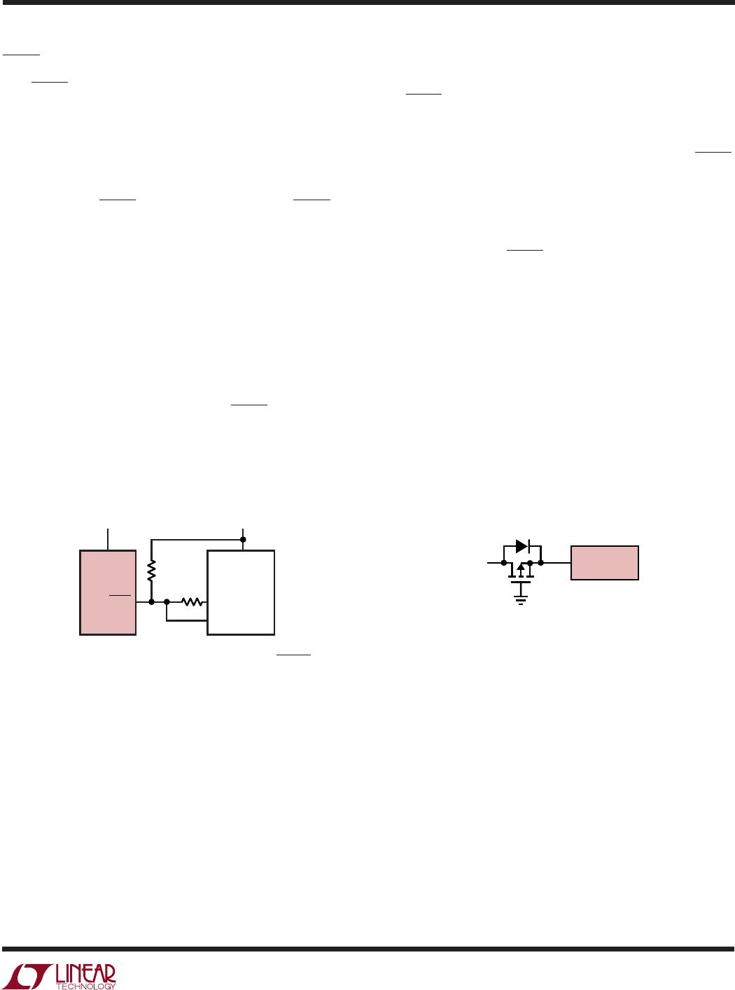
Figure 5. Using a Microprocessor to Determine CHRG State
CHRG Status Output Pin
The CHRG pin can provide an indication that the input
voltage is greater than the undervoltage lockout threshold
level. A weak pull-down current of approximately 20µA
indicates that sufficient voltage is applied to V
CC
to begin
charging. When a discharged battery is connected to the
charger, the constant current portion of the charge cycle
begins and the CHRG pin pulls to ground. The CHRG pin
can sink up to 10mA to drive an LED that indicates that a
charge cycle is in progress.
When the battery is nearing full charge, the charger enters
the constant-voltage portion of the charge cycle and the
charge current begins to drop. When the charge current
drops below 1/10 of the programmed current, the charge
cycle ends and the strong pull-down is replaced by the
20µA pull-down, indicating that the charge cycle has
ended. If the input voltage is removed or drops below the
undervoltage lockout threshold, the CHRG pin becomes
high impedance. Figure 5 shows that by using two
different value pull-up resistors, a microprocessor can
detect all three states from this pin.
APPLICATIO S I FOR ATIO
WUUU
Information furnished by Linear Technology Corporation is believed to be accurate and reliable.
However, no responsibility is assumed for its use. Linear Technology Corporation makes no represen-
tation that the interconnection of its circuits as described herein will not infringe on existing patent rights.
Figure 6. Low Loss Input Reverse Polarity Protection
V
IN
V
CC
LTC4054
DRAIN-BULK
DIODE OF FET
4054 F06
CHRG OUT
IN
2k
800k
405442 F05
LTC4054 µPROCESSOR
V
+
V
DD
V
CC
To detect when the LTC4054 is in charge mode, force the
digital output pin (OUT) high and measure the voltage at
the CHRG pin. The N-channel MOSFET will pull the pin
voltage low even with the 2k pull-up resistor. Once the
charge cycle terminates, the N-channel MOSFET is turned
off and a 20µA current source is connected to the CHRG
pin. The IN pin will then be pulled high by the 2k pull-up
resistor. To determine if there is a weak pull-down current,
the OUT pin should be forced to a high impedance state.
The weak current source will pull the IN pin low through
the 800k resistor; if CHRG is high impedance, the IN pin
will be pulled high, indicating that the part is in a UVLO
state.
Reverse Polarity Input Voltage Protection
In some applications, protection from reverse polarity
voltage on V
CC
is desired. If the supply voltage is high
enough, a series blocking diode can be used. In other
cases, where the voltage drop must be kept low a P-
channel MOSFET can be used (as shown in Figure 6).