April 2005 13 M9999-041405
KS8721CL Micrel, Inc.
asserted. For 10BASE-T links, CRS assertion is based on reception of valid preamble, and de-assertion on reception of an
end-of-frame (EOF) marker.
Collision: Whenever the line state is half-duplex and the transmitter and receiver are active at the same time, the KS8721CL
asserts its collision signal, which is asynchronous to any clock.
RMII (Reduced MII) Data Interface
RMII interface specifies a low-pin count, Reduced Media Independent Interface (RMII) intended for use between Ethernet
PHYs and Switch or Repeater ASICs. It is fully compliant with IEEE 802.3u [2].
This interface has the following characteristics:
It is capable of supporting 10Mbps and 100Mbps data rates.
•A single clock reference is sourced from the MAC to PHY (or from an external source).
It provides independent 2-bit wide (di-bit) transmit and receive data paths.
It uses TTL signal levels compatible with common digital CMOS ASIC processes.
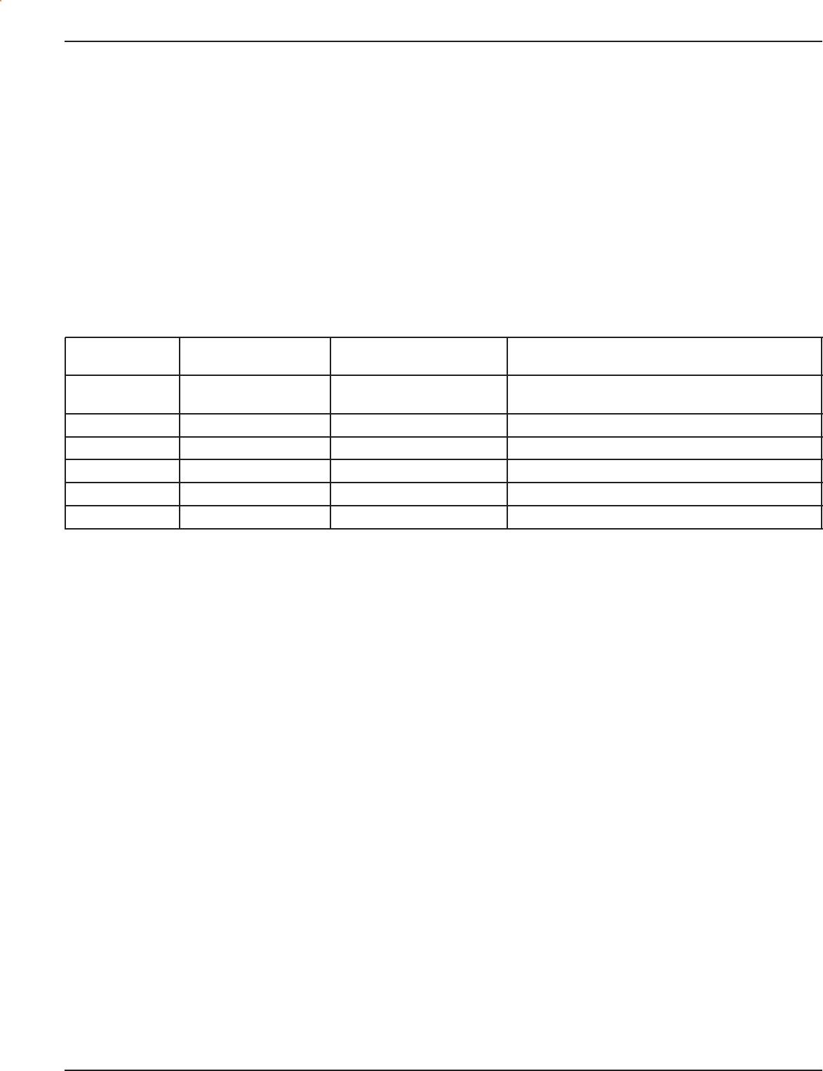
RMII Signal Definition
Direction Direction
Signal Name (w/respect to the PHY) (w/respect to the MAC) Use
REF_CLK Input Input or Output Synchronous clock reference for receive, transmit and
control interface
CRS_DV Output Input Carrier Sense/Receive Data Valid
RXD[1:0] Output Input Receive Data
TX_EN Input Output Transmit Enable
TXD[1:0] Input Output Transmit Data
RX_ER Output Input (Not Required) Receive Error
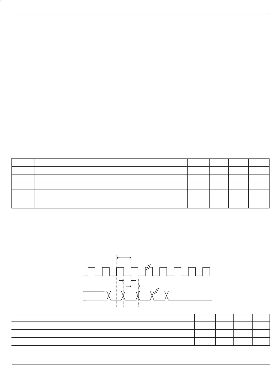
Reference Clock (REF_CLK)
REF_CLK is a continuous 50MHz clock that provides the timing reference for CRS_DV, RXD[1:0], TX_EN, TXD[1:0], and
RX_E. REF_CLK is sourced by the MAC or an external source. Switch implementations may choose to provide REF_CLK as
an input or an output depending on whether they provide a REF_CLK output or rely on an external clock distribution device.
Each PHY device must have an input corresponding to this clock but may use a single clock input for multiple PHYs
implemented on a single IC.
Carrier Sense/Receive Data Valid (CRS_DV)
CRS_DV is asserted asynchronously on detection of carrier due to the criteria relevant to the operating mode. That is, in
10BASE-T mode, when squelch is passed or in 100BASE-X mode when 2 noncontiguous zeroes in 10 bits are detected, the
carrier is detected.
Loss-of-carrier results in the de-assertion of CRS_DV synchronous to REF_CLK. As carrier criteria are met, CRS_DV remains
continuously asserted from the first recovered di-bit of the frame through the final recovered di-bit and is negated prior to the
first REF_CLK that follows the final di-bit.
The data on RXD[1:0] is considered valid once CRS_DV is asserted. However, since the assertion of CRS_DV is asynchronous
relative to REF_CLK, the data on RXD[1:0] remains as “00” until proper receive signal decoding takes place (see “Definition
of RXD[1:0] Behavior”).
Receive Data [1:0] (RXD[1:0])
RXD[1:0] transitions synchronously to REF_CLK. For each clock period in which CRS_DV is asserted, RXD[1:0] transfers two
bits of recovered data from the PHY. In some cases (e.g., before data recovery or during error conditions), a predetermined
value for RXD[1:0] is transferred instead of recovered data. RXD[1:0] remains as “00” to indicate idle when CRS_DV is de-
asserted. Values of RXD[1:0] other than “00” when CRS_DV is de-asserted are reserved for out-of-band signalling (to be
defined). Values other than “00” on RXD[1:0] while CRS_DV is de-asserted are ignored by the MAC/repeater. Upon assertion
of CRS_DV, the PHY ensures that RXD[1:0]=00 until proper receive decoding takes place.
Transmit Enable (TX_EN)
Transmit Enable TX_EN indicates that the MAC is presenting di-bits on TXD[1:0] on the RMII for transmission. TX_EN is
asserted synchronously with the first nibble of the preamble and remains asserted while all transmitted di-bits are presented
KS8721CL Micrel, Inc.
M9999-041405 14 April 2005
to the RMII. TX_EN is negated prior to the first REF_CLK following the final di-bit of a frame. TX_EN transitions synchronously
with respect to REF_CLK.
Transmit Data [1:0] (TXD[1:0])
Transmit Data TXD[1:0] transitions synchronously with respect to REF_CLK. When TX_EN is asserted, TXD[1:0] are accepted
for transmission by the PHY. TXD[1:0] remains as “00” to indicate idle when TX_EN is de-asserted. Values of TXD[1:0] other
than “00” when TX_EN is de-asserted are reserved for out-of-band signalling (to be defined). Values other than “00” on
TXD[1:0] while TX_EN is de-asserted are ignored by the PHY.
Collision Detection
Since the definition of CRS_DV and TX_EN both contain an accurate indication of the start of frame, the MAC reliably
regenerates the COL signal of the MII by ending TX_EN and CRS_DV.
During the IPG time following the successful transmission of a frame, the COL signal is asserted by some transceivers as a
self-test. The Signal Quality Error (SQE) function is not supported by the reduced MII due to the lack of the COL signal.
Historically, SQE was present to indicate that a transceiver located physically remote from the MAC was functioning. Since
the reduced MII only supports chip-to-chip connections on a PCB, SQE functionality is not required.
RX_ER
The PHY provides RX_ER as an output according to the rules specified in IEEE 802.3u [2] (see Clause 24, Figure 24-11–
Receive State Diagram). RX_ER is asserted for one or more REF_CLK periods to indicate that an error (e.g., a coding error
or any error that a PHY is capable of detecting, and that may otherwise be undetectable by the MAC sublayer) is detected
somewhere in the frame presently being transferred from the PHY. RX_ER transitions synchronously with respect to
REF_CLK. While CRS_DV is de-asserted, RX_ER has no effect on the MAC.
RMII AC Characteristics
Symbol Parameter Min Typ Max Unit
REF_CLK Frequency 50 MHz
REF_CLK Duty Cycle 35 65 %
t
SU
TXD[1:0], TX_EN, RXD[1:0], CRS_DV, RXER 4 ns
t
H
TXD[1:0], TX_EN, RXD[1:0], CRS_DV, RXER 2 ns
Data Hold from REF_CLK
Rising Edge
Unused RMII Pins
Input Pins TXD[2:3] and TXER are pull-down to GND.
Output Pins RXD[2:3] and RXC are no connect. Note that the RMII pin needs to be pulled up to enable RMII mode.
RMII Transmit Timing
REF_CLK
20ns
TXD[1:0]
TXEN
TXER
t
1
t
2
Parameter Min Typ Max Units
REF_CLK Frequency 50 MHz
TXEN, TXD[1:0], TX_EN, Data Setup to REF_CLK rising edge 4 ns
TXEN, TXD[1:0], TX_EN, Data hold from REF_CLK rising edge 2 ns
April 2005 15 M9999-041405
KS8721CL Micrel, Inc.
RMII Receive Timing
REF_CLK
20ns
t
od
RXD[1:0]
RXDV
RXER
Parameter Min Typ Max Units
REF_CLK Frequency 50 MHz
RXD[1:0], CRS_DV, RX_ER Output delay from REF_CLK rising edge 2.8 10 ns
Auto-Crossover (Auto-MDI/MDI-X)
Automatic MDI/MDI-X configuration is intended to eliminate the need for crossover cables between similar devices. The
assignment of pinouts for a 10BASE-T/100BASE-TX crossover function cable is shown below.
This feature eliminates the confusion in applications by allowing the use of both straight and crossover cables. This feature
is controlled by register 1f:13. See the “Register 1fh–100BASE-TX PHY Controller” section for details.
Receive Pair
Transmit Pair
Receive Pair
1
2
3
4
5
6
7
8
1
2
3
4
5
6
7
8
Transmit Pair
(RJ-45)
NIC
Straight
Cable
10/100 Ethernet
Media Dependent Interface
10/100 Ethernet
Media Dependent Interface
Modular Connector
(RJ-45)
HUB
(Repeater or Switch)
Modular Connector
Figure 1. Straight Through Cable
Receive Pair Receive Pair
Transmit Pair
1
2
3
4
5
6
7
8
1
2
3
4
5
6
7
8
Transmit Pair
Modular Connector (RJ-45)
HUB
(Repea ter or Switch)
Modular Connector (RJ-45)
HUB
(Repeater or Switch)
Crossover
Cable
10/100 Ethernet
Media Dependent Interface
10/100 Ethernet
Media Dependent Interface
Figure 2. Crossover Cable

KSZ8721CL

Mfr. #:
Manufacturer:
Microchip Technology / Micrel
Description:
Ethernet ICs 10/100 BASE-TX/FX Physical Layer Transceiver
Lifecycle:
New from this manufacturer.
Delivery:
DHL FedEx Ups TNT EMS
Payment:
T/T Paypal Visa MoneyGram Western Union