Interface Connectors
The host interface connector conforms to the PCIe Electromechanical Specification
V2.0, section 5, Table 5-1. It is an eight-lane, gold-finger connector with 1mm pitch
spacing.
A mechanical indent is used to separate the PCIe power pins from the differential signal
contacts. The pins are numbered below in ascending order from left to right. Side B re-
fers to component side and Side A refers to the solder side.
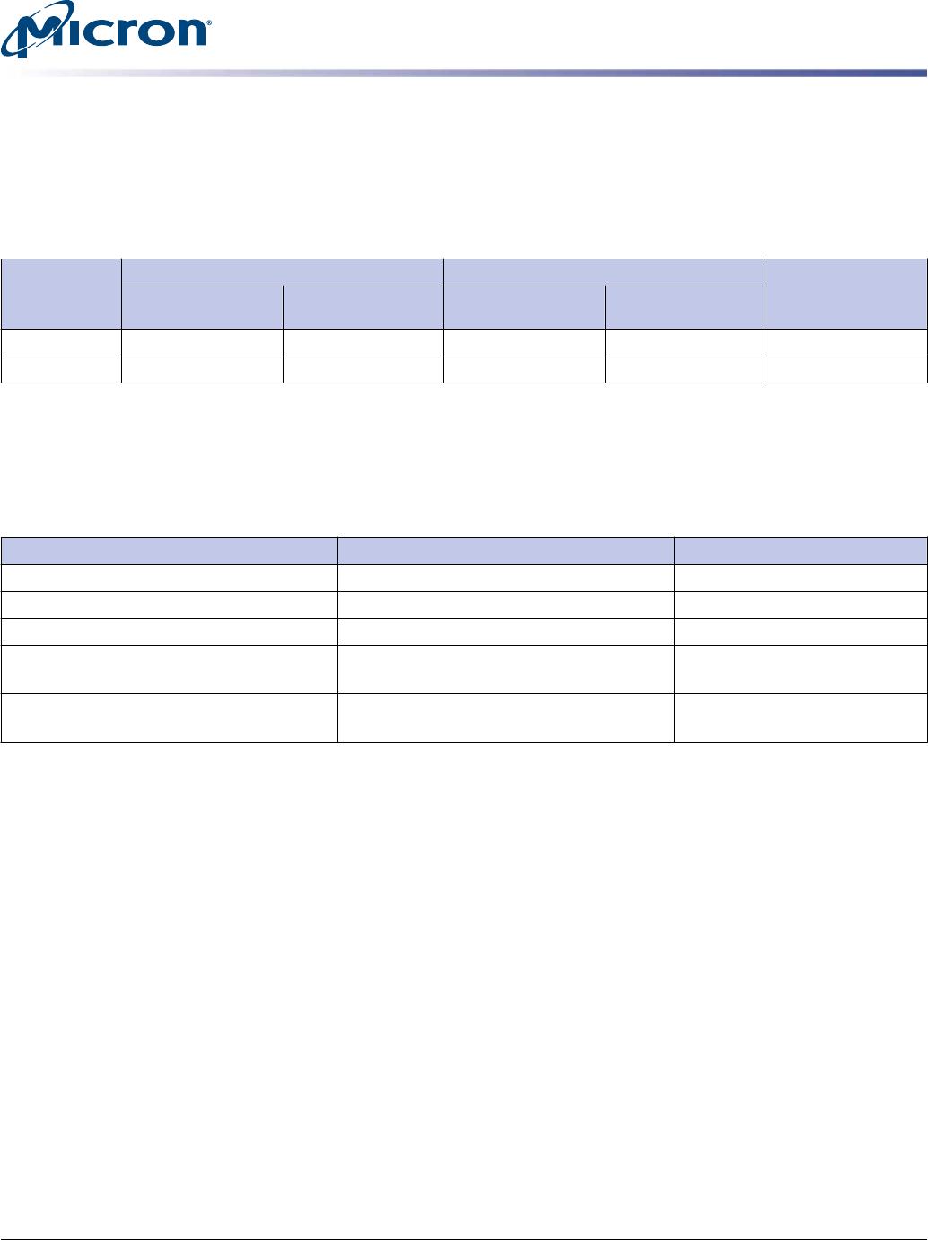
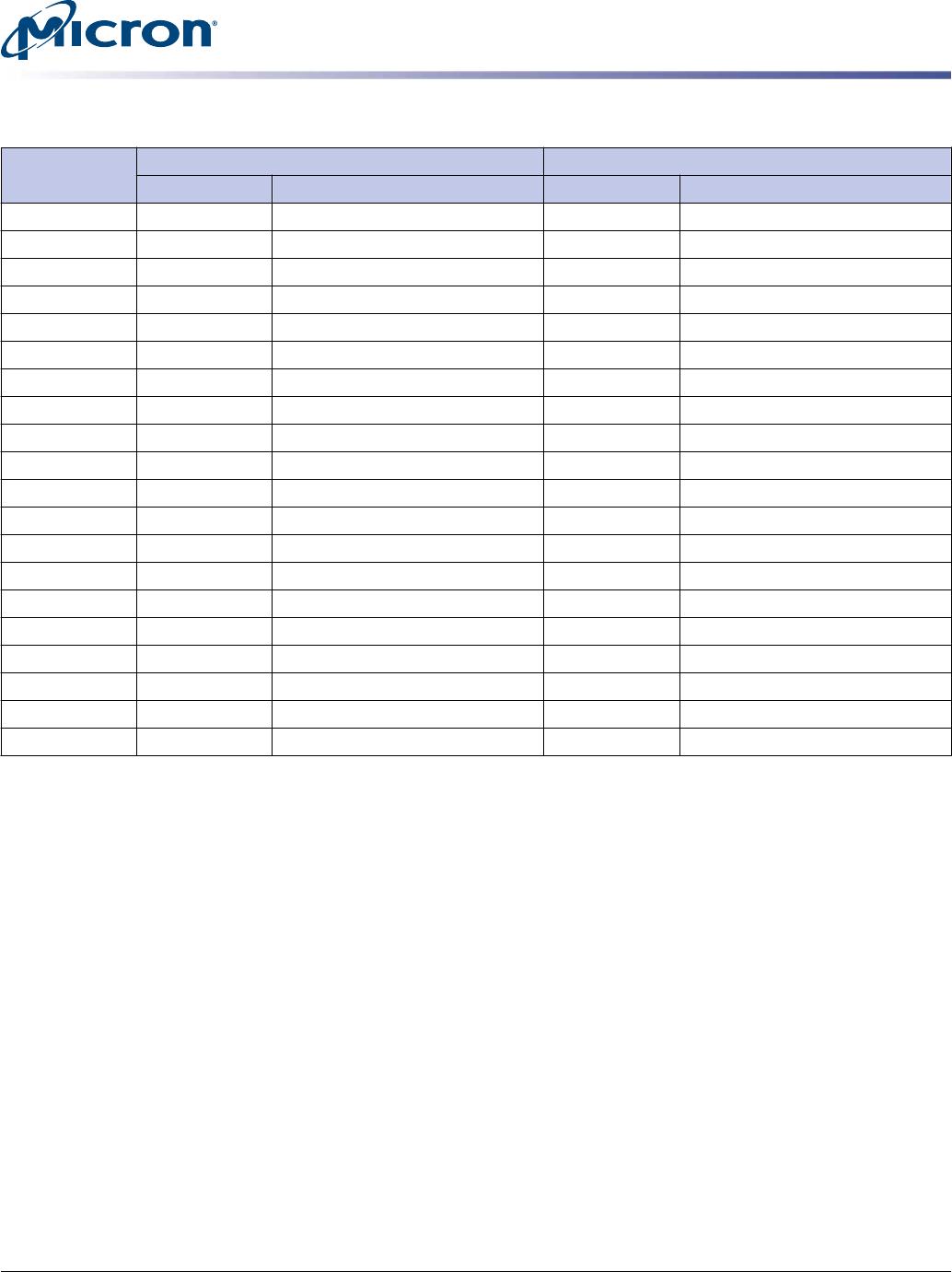
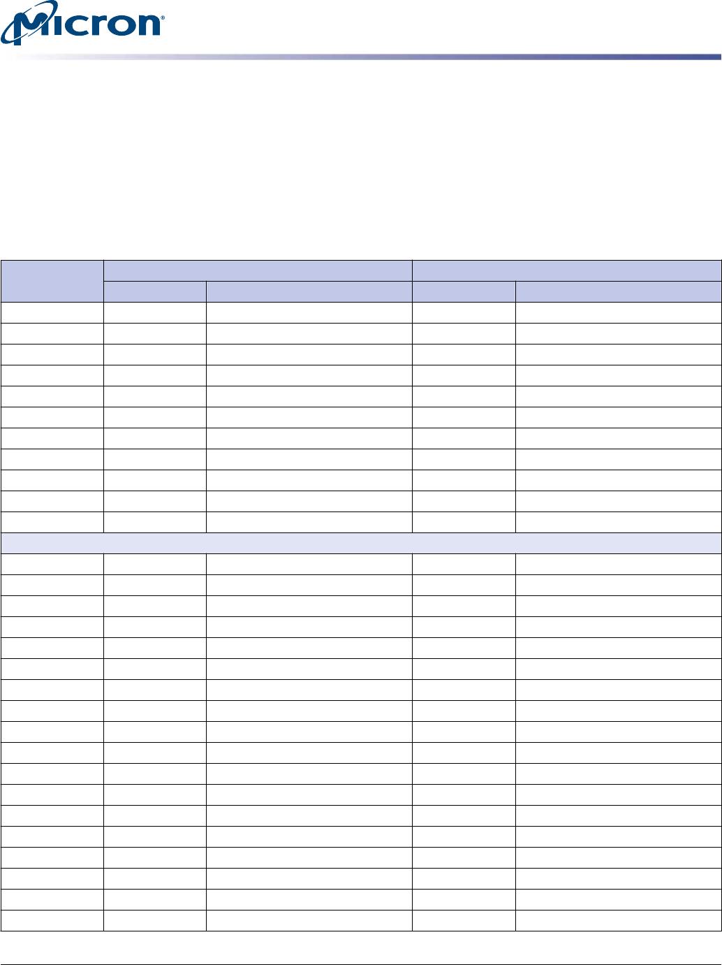
Table 6: PCIe Interface Connector Pin Assignments
Pin
Number
Side B Side A
Name Description Name Description
1 +12V 12V power PRSNT1# Hot Plug Presence Detect
2 +12V 12V power +12V 12V power
3 +12V 12V power +12V 12V power
4 GND Ground GND Ground
5 SMCLK DNU JTAG2 DNU
6 SMDAT DNU JTAG3 DNU
7 GND Ground JTAG4 DNU
8 +3.3V DNU JTAG5 DNU
9 JTAG1 DNU +3.3V DNU
10 3.3Vaux DNU +3.3V DNU
11 WAKE# DNU PERST# PCIe Reset
Mechanical Key
12 RSVD Reserved GND Ground
13 GND Ground REFCLK+ PCIe REFCLK p
14 PETp0 PCIe TX Lane 0 p REFCLK- PCIe REFCLK n
15 PETn0 PCIe TX Lane 0 n GND Ground
16 GND Ground PERp0 PCIe RX Lane 0 p
17 PRSNT2# Hot Plug Presence Detect PERn0 PCIe RX Lane 0 n
18 GND Ground GND Ground
19 PETp1 PCIe TX Lane 1 p RSVD Reserved
20 PETn1 PCIe TX Lane 1 n GND Ground
21 GND Ground PERp1 PCIe RX Lane 1 p
22 GND Ground PERn1 PCIe RX Lane 1 n
23 PETp2 PCIe TX Lane 2 p GND Ground
24 PETn2 PCIe TX Lane 2 n GND Ground
25 GND Ground PERp2 PCIe RX Lane 2 p
26 GND Ground PERn2 PCIe RX Lane 2 n
27 PETp3 PCIe TX Lane 3 p GND Ground
28 PETn3 PCIe TX Lane 3 p GND Ground
29 GND Ground PERp3 PCIe RX Lane 3 p
P320h HHHL PCIe NAND SSD
Interface Connectors
PDF: 09005aef848cbdf4
realssd_p320h_hhhl_distribution.pdf - Rev. V 8/2014 EN
8
Micron Technology, Inc. reserves the right to change products or specifications without notice.
© 2011 Micron Technology, Inc. All rights reserved.