6
Absolute Maximum Ratings
(No Derating Required up to 55°C)
Description Min. Typ. Max. Units
Storage Temperature -55°C +125°C T
S
Operating Temperature -40°C +85°C T
A
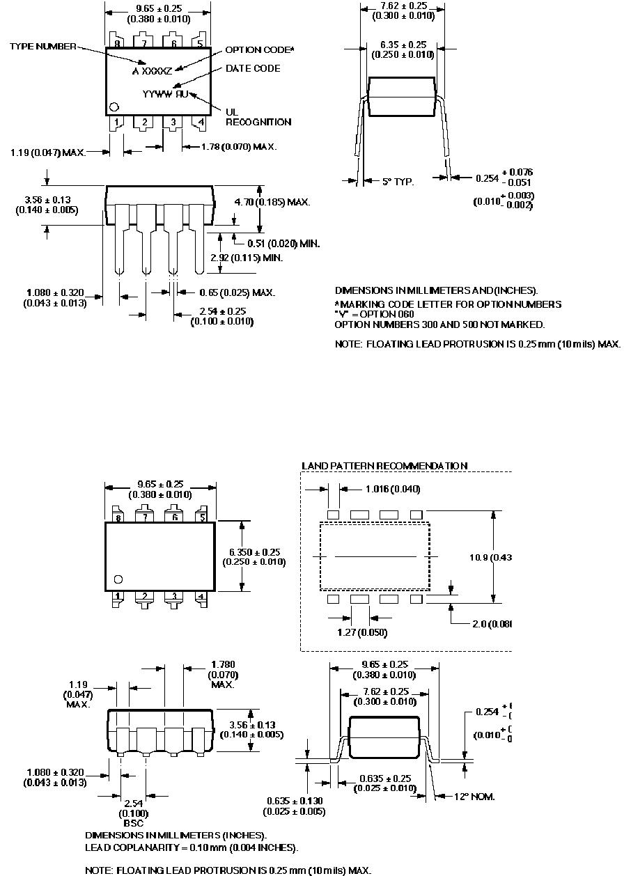
Lead Solder Temperature
(1.6 mm below seating plane)
260°C for 10 s max
Average Forward Input Current 5 mA
[2]
- I
F
Reverse Input Voltage 3.0 V V
R
Supply Voltage 0 V 7.0 V V
CC
Pull-Up Resistor Voltage -0.5 V VCC V
RL
Output Collector Current -25 mA 25 mA I
O
Input Power Dissipation 10 mW P
I
Output Collector Power Dissipation 40 mW P
O
Output Collector Voltage -0.5 V 18 V V
O
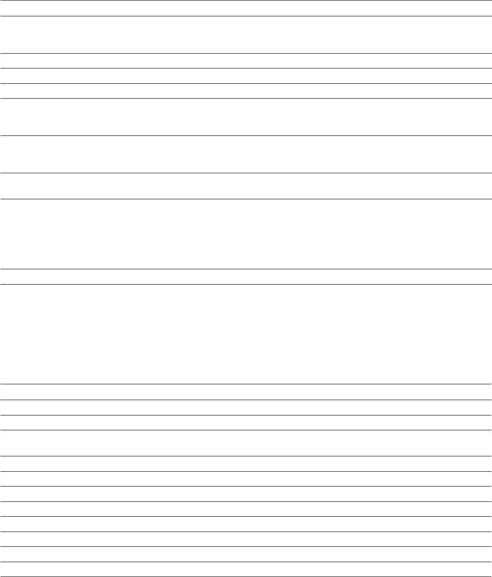
Infrared and Vapor Phase Reow Temperature (Option #300) see Fig. 1, Thermal Prole
IEC/EN/DIN EN 60747-5-5 Insulation Related Characteristics (HCPL-2300 Option 060 only)
Description Symbol Characteristic Units
Installation classication per DIN VDE 0110/39, Table 1
for rated mains voltage ≤300 V
rms
for rated mains voltage ≤600 V
rms
I-IV
I-IV
Climatic Classication 55/85/21
Pollution Degree (DIN VDE 0110/39) 2
Maximum Working Insulation Voltage V
IORM
630 V
peak
Input to Output Test Voltage, Method b*
V
IORM
x 1.875 = V
PR
, 100% Production Test with t
m
= 1 sec,
Partial Discharge < 5 pC
V
PR
1181 V
peak
Input to Output Test Voltage, Method a*
V
IORM
x 1.6 = V
PR
, Type and sample test, t
m
= 10 sec,
Partial Discharge < 5 pC
V
PR
1008 V
peak
Highest Allowable Overvoltage*
(Transient Overvoltage, t
ini
= 60 sec)
V
IOTM
8000 V
peak
Safety Limiting Values
(Maximum values allowed in the event of a failure,
also see Figure 11, Thermal Derating curve.)
Case Temperature
Input Current
Output Power
T
S
I
S,INPUT
P
S,OUTPUT
175
230
600
°C
mA
mW
Insulation Resistance at TS, VIO = 500 V RS ≥109
Ω
*Refer to the front of the optocoupler section of the current catalog, under Product Safety Regulations section, IEC/EN/DIN EN 60747-5-5, for a
detailed description.
Note:
Isolation characteristics are guaranteed only within the safety maximum ratings which must be ensured by protective circuits in application.