8
LTC3401
3401fb
APPLICATIO S I FOR ATIO
WUUU
Current Sensing. Lossless current sensing converts the
peak current signal to a voltage to sum in with the internal
slope compensation. This summed signal is compared to
the error amplifier output to provide a peak current control
command for the PWM. The slope compensation in the IC
is adaptive to the input and output voltage. Therefore, the
converter provides the proper amount of slope compensa-
tion to ensure stability and not an excess causing a loss of
phase margin in the converter.
Error Amp. The error amplifier is a transconductance
amplifier with g
m
= 0.1ms. A simple compensation net-
work is placed from the V
C
pin to ground.
Current Limit. The current limit amplifier will shut the
NMOS switch off once the current exceeds its threshold.
The current amplifier delay to output is typically 50ns.
Zero Current Amp. The zero current amplifier monitors the
inductor current to the output and shuts off the synchro-
nous rectifier once the current is below 50mA, preventing
negative inductor current.
Antiringing Control. The anitringing control will place an
impedance across the inductor to damp the ringing on the
SW pin during discontinuous mode operation. The LC
SW
ringing (L = inductor, C
SW
= capacitance on the switch pin)
is low energy, but can cause EMI radiation.
Burst Mode Operation
Burst Mode operation is when the IC delivers energy to the
output until it is regulated and then goes into a sleep mode
where the outputs are off and the IC is consuming only
38μA. In this mode, the output ripple has a variable
frequency component with load current and the steady
state ripple will be typically below 3%.
During the period where the device is delivering energy to
the output, the peak current will be equal to 1/3 the current
limit value and the inductor current will terminate at zero
current for each cycle. In this mode the maximum output
current is given by:
I
V
V
Amps
OUT MAXBURST
IN
OUT
()
•
≈
6
DETAILED DESCRIPTION
The LTC3401 provides high efficiency, low noise power
for applications such as portable instrumentation. The
current mode architecture with adaptive slope compensa-
tion provides ease of loop compensation with excellent
transient load response. The low R
DS(ON)
, low gate charge
synchronous switches provide the pulse width modula-
tion control at high efficiency.
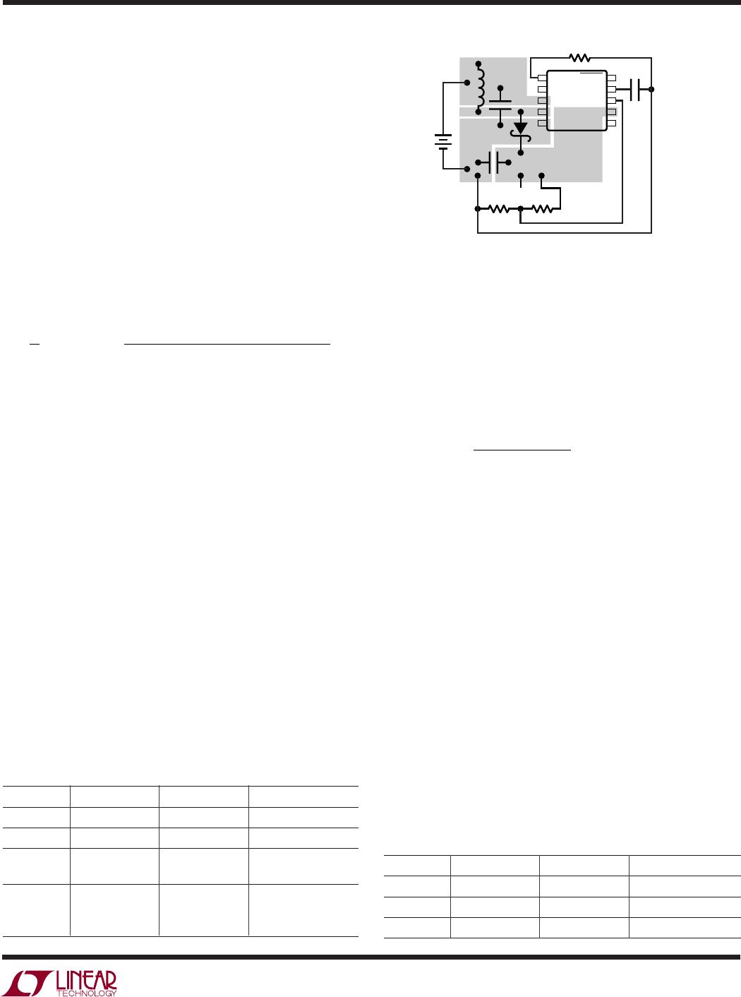
The Schottky diode across the synchronous PMOS switch
provides a lower drop during the break-before-make time
(typically 20ns) of the NMOS to PMOS transition. The
Schottky diode improves efficiency (see graph “Efficiency
loss without Schottky vs Frequency”). While the IC’s
quiescent current is a low 38μA, high efficiency is achieved
at light loads when Burst Mode operation is entered.
Low Voltage Start-Up
The LTC3401 is designed to start up at input voltages of
typically 0.85V. The device can start up under some load,
(see graph “Start-Up vs Input Voltage”). Once the output
voltage exceeds a threshold of 2.3V, the IC powers itself
from V
OUT
instead of V
IN
. At this point, the internal circuitry
has no dependency on the V
IN
input voltage, eliminating
the requirement for a large input capacitor. The input
voltage can drop below 0.5V without affecting the opera-
tion, but the limiting factor for the application becomes the
availability of the power source to supply sufficient energy
to the output at the low voltages.
Low Noise Fixed Frequency Operation
Oscillator. The frequency of operation is set through a
resistor from the R
t
pin to ground:
f = 3 • 10
10
/R
t
An internally trimmed timing capacitor resides inside the
IC. The oscillator can be synchronized with an external
clock inserted on the MODE/SYNC pin. When synchroniz-
ing the oscillator, the free running frequency must be set
to approximately 30% lower than the desired synchro-
nized frequency. Keeping the sync pulse width below 2μs
will ensure that Burst Mode operation is disabled.