MAX2140
Complete SDARS Receiver
4 _______________________________________________________________________________________
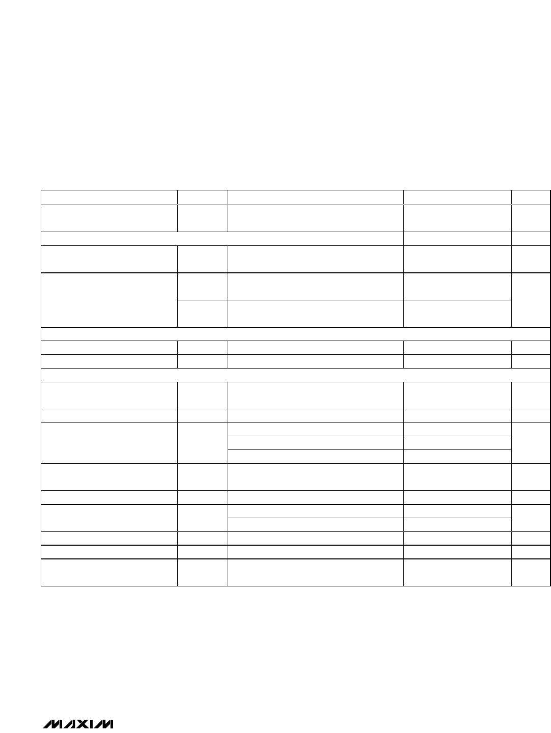
AC ELECTRICAL CHARACTERISTICS (continued)
(MAX2140 EV kit, current drawn at VOUTANT, I
VOUTANT
= 150mA max, V
CC
= 3.1V to 3.6V, VINANT = 3.1V to 5.3V, f
RF
= 2320MHz
to 2345MHz, f
LO
= 2076MHz, T
A
= -40°C to +85°C. Typical values are at V
CC
= VINANT = 3.3V, f
RF
= 2338MHz, T
A
= +25°C, unless
otherwise noted.) (Note 2)
Interstage (IF) 259MHz SAW filter specification: insertion loss = 19dB max, 9.3MHz to 12MHz from center attenuation = 24dB min,
beyond 12MHz from center attenuation = 40dB min.
PARAMETER SYMBOL CONDITIONS MIN TYP MAX UNITS
RF AGC is at maximum gain,
IF AGC is at reference gain
+1
RF AGC is at maximum gain,
IF AGC is at reference gain -5dB
+6
In-Band Input IP2 (Notes 5, 6) I_IIP2
RF AGC is at maximum gain,
IF AGC is at reference gain -25dB
+27
dBm
RF AGC is at maximum gain,
IF AGC is at reference gain
+38
RF AGC is at maximum gain -7dB,
IF AGC is at reference gain
+45
Out-of-Band Input IP2
(Notes 5, 7)
O_IIP2
RF AGC is at maximum gain -25dB,
IF AGC is at reference gain
+60
dBm
Opposite Sideband Rejection OSR Baseband frequencies = 100kHz (Note 4) 32 39 dB
Image Rejection IRej At f
LO
- f
IF
54 dB
Half IF Rejection HRej At f
LO
+ 0.5 x f
IF
53 dB
RF AGC LOOP
LNA Gain Reduction
RFAGC_
Range
(Note 4) 30 42 dB
Minimum RF AGC Trip Point RFAGC_min Bits RF4/3/2/1/0 = 00000 (BIN) -35 dBm
RF AGC Trip Point RFAGC_int Bits RF4/3/2/1/0 = 00010 (BIN) (Note 4) -37 -33 -29 dBm
Maximum RF AGC Trip Point RFAGC_max Bits RF4/3/2/1/0 = 10100 (BIN) -15 dBm
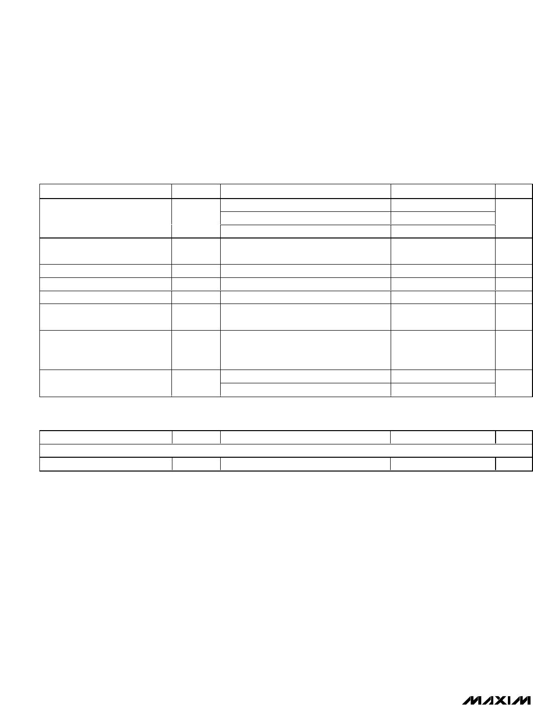
FRONT-END (FE) PROGRAMMABLE GAIN
FE Programmable Gain Range FE_Rge (Note 4) 19 22 26 dB
FE Programmable Gain Step FE_Step 2 dB
IF FILTER INTERFACE
IF Output Differential Admittance Yout, IF
Between pins IFOUT+, IFOUT-,
f
IF
= 259MHz and 467MHz
1/900
+ j0
S
Input Differential Impedance
Presented by the IC to the IF
Filter Output
Zin, IF
Between pins IFOUT+, IFOUT-,
f
IF
= 259MHz and 467MHz
150
+ j0
Ω
IF AGC LOOP
IF AGC Control Voltage for Max
Gain
IFAGC_VM Applied at pin AGCPWM 0.2 V
IF AGC Control Voltage for Min
Gain
IFAGC_Vm Applied at pin AGCPWM 2.5 V