MP1470
High-Efficiency, 2A, 16V, 500kHz
Synchronous, Step-Down Converter
In a 6-Pin TSOT 23
MP1470 Rev. 1.02 www.MonolithicPower.com 1
8/27/2013 MPS Proprietary Information. Patent Protected. Unauthorized Photocopy and Duplication Prohibited.
© 2013 MPS. All Rights Reserved.
The Future of Analog IC Technology
DESCRIPTION
The MP1470 is a high-frequency, synchronous,
rectified, step-down, switch-mode converter
with internal power MOSFETs. It offers a very
compact solution to achieve a 2A continuous
output current over a wide input supply range,
with excellent load and line regulation. The
MP1470 has synchronous-mode operation for
higher efficiency over the output current-load
range.
Current-mode operation provides fast transient
response and eases loop stabilization.
Protection features include over-current
protection and thermal shutdown.
The MP1470 requires a minimal number of
readily-available, standard, external
components and is available in a space-saving
6-pin TSOT23 package.
FEATURES
Wide 4.7V-to-16V Operating Input Range
163m/86m Low-R
DS(ON)
Internal Power
MOSFETs
Proprietary Switching-Loss–Reduction
Technique
High-Efficiency Synchronous-Mode
Operation
Fixed 500kHz Switching Frequency
Internal AAM Power-Save Mode for High
Efficiency at Light Load
Internal Soft-Start
Over-Current Protection and Hiccup
Thermal Shutdown
Output Adjustable from 0.8V
Available in a 6-pin TSOT-23 package
APPLICATIONS
Game Consoles
Digital Set-Top Boxes
Flat-Panel Television and Monitors
General Purposes
All MPS parts are lead-free and adhere to the RoHS directive. For MPS green
status, please visit MPS website under Products, Quality Assurance page.
“MPS” and “The Future of Analog IC Technology” are registered trademarks of
Monolithic Power Systems, Inc.
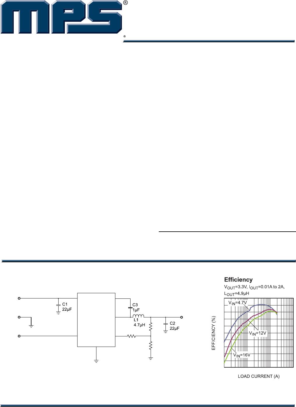
TYPICAL APPLICATION
VIN
R2
13k
R1
40.2k
R3
75k
IN
U1
GND
MP1470
1
4
VOUT
2
6
3
5
EN
FB
SW
BST
3.3V/2A
EN
GND
50
55
60
65
70
75
80
85
90
95
100
0.01 0.1 1 10
MP1470 – SYNCHRONOUS, STEP-DOWN CONVERTER WITH INTERNAL MOSFETS
MP1470 Rev. 1.02 www.MonolithicPower.com 2
8/27/2013 MPS Proprietary Information. Patent Protected. Unauthorized Photocopy and Duplication Prohibited.
© 2013 MPS. All Rights Reserved.
ORDERING INFORMATION
Part Number* Package Top Marking
MP1470GJ TSOT23-6 ADJ
* For Tape & Reel, add suffix –Z (e.g. MP1470GJ–Z);
PACKAGE REFERENCE
TOP VIEW
1
2
3
6
5
4
MP1470
BST
SW
IN
GND
FB
EN
MP1470
ABSOLUTE MAXIMUM RATINGS
(1)
V
IN
..................................................-0.3V to 17V
V
SW
......................................................................
-0.3V (-5V for <10ns) to 17V (19V for <10ns)
V
BS
......................................................... V
SW
+6V
All Other Pins...................................–0.3V to 6V
Continuous Power Dissipation (T
A
= +25°C)
(2)
........................................................... 1.25W
Junction Temperature...............................150°C
Lead Temperature ....................................260°C
Storage Temperature................. -65°C to 150°C
Recommended Operating Conditions
(3)
Supply Voltage V
IN
...........................4.7V to 16V
Output Voltage V
OUT
......................0.8V to 0.9V
IN
Operating Junction Temp. (T
J
). -40°C to +125°C
Thermal Resistance
(4)
θ
JA
θ
JC
TSOT-23-6............................. 100 ..... 55... °C/W
Notes:
1) Exceeding these ratings may damage the device.
2) The maximum allowable power dissipation is a function of the
maximum junction temperature T
J
(MAX), the junction-to-
ambient thermal resistance
JA
, and the ambient temperature
T
A
. The maximum allowable continuous power dissipation at
any ambient temperature is calculated by P
D
(MAX) = (T
J
(MAX)-T
A
)/
JA
. Exceeding the maximum allowable powe
r
dissipation will cause excessive die temperature, and the
regulator will go into thermal shutdown. Internal thermal
shutdown circuitry protects the device from permanent
damage.
3) The device is not guaranteed to function outside of its
operating conditions.
4) Measured on JESD51-7, 4-layer PCB.
MP1470 – SYNCHRONOUS, STEP-DOWN CONVERTER WITH INTERNAL MOSFETS
MP1470 Rev. 1.02 www.MonolithicPower.com 3
8/27/2013 MPS Proprietary Information. Patent Protected. Unauthorized Photocopy and Duplication Prohibited.
© 2013 MPS. All Rights Reserved.
ELECTRICAL CHARACTERISTICS
(5)
V
IN
= 12V, T
A
= 25°C, unless otherwise noted.
Parameter Symbol Condition Min Typ Max Units
Supply Current (Shutdown) I
IN
V
EN
= 0V 1 A
Supply Current (Quiescent) I
q
V
EN
= 2V, V
FB
= 1V 0.83 mA
HS Switch-On Resistance HS
RDS-ON
V
BST-SW
=5V 163 m
LS Switch-On Resistance LS
RDS-ON
Vcc=5V 86 m
Switch Leakage SW
LKG
V
EN
= 0V, V
SW
=12V 1 A
Current Limit
(5)
I
LIMIT
3 3.7 A
Oscillator Frequency f
SW
V
FB
=0.75V 400 490 580 kHz
Maximum Duty Cycle D
MAX
V
FB
=700mV 88 92 %
Minimum On Time
(5)
ON_MIN
90 ns
Feedback Voltage V
FB
776 800 824 mV
EN Rising Threshold V
EN_RISING
1.4 1.5 1.6 V
EN Falling Threshold V
EN_FALLING
1.23 1.32 1.41 V
V
EN
=2V 1.6 A
EN Input Current I
EN
V
EN
=0 0 A
V
IN
Under-Voltage Lockout
Threshold—Rising
INUV
Vth
3.85 4.2 4.55 V
V
IN
Under-Voltage Lockout
Threshold Hysteresis
INUV
HYS
340 mV
Soft-Start Period
SS
1 ms
Thermal Shutdown
(5)
150 °C
Thermal Hysteresis
(5)
20 °C
Notes:
5) Guaranteed by design.

MP1470GJ-Z

Mfr. #:
Manufacturer:
Monolithic Power Systems (MPS)
Description:
Switching Voltage Regulators 2A, 16V, 500kHz Sync, Stp-Dwn Cnvrtr
Lifecycle:
New from this manufacturer.
Delivery:
DHL FedEx Ups TNT EMS
Payment:
T/T Paypal Visa MoneyGram Western Union

Products related to this Datasheet