MP1470 – SYNCHRONOUS, STEP-DOWN CONVERTER WITH INTERNAL MOSFETS
MP1470 Rev. 1.02 www.MonolithicPower.com 9
8/27/2013 MPS Proprietary Information. Patent Protected. Unauthorized Photocopy and Duplication Prohibited.
© 2013 MPS. All Rights Reserved.
OPERATION
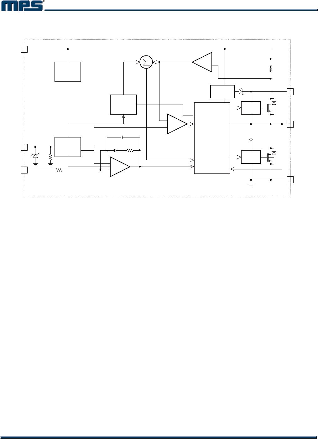
The MP1470 is a high-frequency, synchronous,
rectified, step-down, switch-mode converter
with internal power MOSFETs. It offers a very
compact solution to achieve a 2A continuous
output current over a wide input supply range,
with excellent load and line regulation.
The MP1470 operates in a fixed-frequency,
peak-current–control mode to regulate the
output voltage. An internal clock initiates the
PWM cycle to turn on the integrated high-side
power MOSFET. This MOSFET remains on
until its current reaches the value set by the
COMP voltage. When the power switch is off, it
remains off until the next clock cycle starts. If
the current in the power MOSFET does not
reach the COMP set current value within 90%
of one PWM period, the power MOSFET is
forced to turn off.
Internal Regulator
The 5V internal regulator powers most of the
internal circuits. This regulator takes V
IN
and
operates in the full V
IN
range. When V
IN
exceeds 5.0V, the regulator output is in full
regulation. When V
IN
falls below 5.0V, the
output decreases.
Error Amplifier
The error amplifier compares the FB voltage
against the internal 0.8V reference (REF) and
outputs a current proportional to the difference
between the two. This output current charges or
discharges the internal compensation network
to form the COMP voltage, which is used to
control the power MOSFET current. The
optimized internal compensation network
minimizes the external component counts and
simplifies the control-loop design.
AAM Operation
The MP1470 has AAM (Advanced
Asynchronous Modulation) power-save mode
for light load. The AAM voltage is set at 0.5V
internally. Under the heavy load condition, the
V
COMP
is higher than V
AAM
. When the clock goes
high, the high-side power MOSFET turns on
and remains on until V
ILsense
reaches the value
set by the COMP voltage. The internal clock
resets every time when V
COMP
is higher than
V
AAM
.
Under the light load condition, the value of
V
COMP
is low. When V
COMP
is less than V
AAM
and
V
FB
is less than V
REF
, V
COMP
ramps up until it
exceeds V
AAM
. During this time, the internal
clock is blocked, thus the MP1470 skips some
pulses for PFM (Pulse Frequency Modulation)
mode and achieves the light load power save.
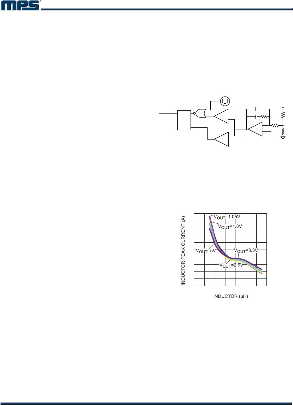
V
AAM
Clock
V
OUT
R1
1.2pF
47pF 500k
20k
R2
V
REF
V
FB
V
IL sense
V
COMP
HS_driver
-
+
+
-
QS
R
+
-
Figure 2: Simplified AAM Control Logic
When the load current is light, the inductor peak
current is set internally to about 380mA for
V
IN
=12V, V
OUT
=3.3V, and L=6.5H. The curve
of inductor peak current vs. inductor is shown in
Figure 3.
Inductor Peak Current
vs. Inductor
0.2
0.3
0.4
0.5
0.6
0.7
0.8
0.9
1
1.1
1.2
01234567
Figure 3: Inductor Peak Current vs. Inductor
Value
Enable
EN is a digital control pin that turns the
regulator on and off: Drive EN HIGH to turn on
the regulator, drive it LOW to turn it off. An
internal 1M resistor from EN to GND allows
EN to float to shut down the chip.
The EN pin is clamped internally using a 6.5V
series-Zener-diode as shown in Figure 4.
Connecting the EN input pin through a pullup