General Description
The MAX66140 combines 1024 bits of user EEPROM
with secure hash algorithm (SHA-1) challenge-and-
response authentication (ISO/IEC 10118-3 SHA-1), a
64-bit unique identifier (UID), one 64-bit secret, and a
13.56MHz ISO 15693 RF interface in a single chip. The
memory is organized as 16 blocks of 8 bytes plus three
more blocks—one for the secret and two for data and
control registers. Except for the secret, each block has
a user-readable write-cycle counter. Four adjacent user
EEPROM blocks form a memory page (pages 0 to 3).
The integrated SHA-1 engine provides a Message
Authentication Code (MAC) using data from the
EEPROM of the device and the 64-bit secret to guaran-
tee secure, symmetric authentication for both reading
and writing to the device. Memory protection features
are write protection and EPROM emulation, which the
user can set for each individual memory page. Page 3
can also be read protected for enhanced authentication
strength. The MAX66140 supports all ISO 15693-
defined data rates, modulation indices, subcarrier
modes, the selected state, application family identifier
(AFI), data storage format identifier (DSFID), and the
Option_flag bit for read operations. Memory write
access (except for AFI, DSFID, and the corresponding
lock bytes) is accomplished through custom com-
mands using a write buffer with readback and copy-to-
memory function.
Applications
Driver Identification (Fleet Application)
Access Control
eCash
Asset Tracking
Features
Fully Compliant with ISO 15693 and ISO 18000-3
Mode 1 Standard
13.56MHz ±7kHz Carrier Frequency
1024-Bit Secure User EEPROM with Block Lock
Feature, Write-Cycle Counter, and Optional
EPROM-Emulation Mode
64-Bit UID
512-Bit SHA-1 Engine to Compute 160-Bit MAC
and to Generate Secrets
Mutual Authentication: Data Read from Device is
Verified and Authenticated by the Host with
Knowledge of the 64-Bit Secret
Read and Write (64-Bit Block)
Supports AFI and DSFID Function
10ms Programming Time
Write: 10% or 100% ASK Modulation Using 1/4
(26kbps) or 1/256 (1.6kbps) Pulse Position Coding
Read: Load Modulation Using Manchester Coding
with 423kHz and 484kHz Subcarrier in Low
(6.6kbps) or High (26kbps) Data-Rate Mode
200,000 Write/Erase Cycles (Minimum)
40-Year Data Retention (Minimum)
Read Compatible with Existing 1Kb ISO 15693
Products on the Market
MAX66140
ISO 15693-Compliant Secure Memory
________________________________________________________________
Maxim Integrated Products
1
IC LOAD
SWITCHED
LOAD
MAGNETIC
COUPLING
ANTENNA
RX_IN
TX_OUT
TRANSMITTER
13.56MHz READER
MAX66140
Typical Operating Circuit
Rev 1; 1/11
For pricing, delivery, and ordering information, please contact Maxim Direct at 1-888-629-4642,
or visit Maxim’s website at www.maxim-ic.com.
ABRIDGED DATA SHEET
Mechanical Drawings appear at end of data sheet.
EVALUATION KIT
AVAILABLE
Ordering Information
+
Denotes a lead(Pb)-free/RoHS-compliant package.
PART TEMP RANGE PIN-PACKAGE
MAX66140E-000AA+ -25°C to +50°C ISO Card
MAX66140K-000AA+ -25°C to +50°C Key Fob
MAX66140
ISO 15693-Compliant Secure Memory
2 _______________________________________________________________________________________
ABRIDGED DATA SHEET
ABSOLUTE MAXIMUM RATINGS
ELECTRICAL CHARACTERISTICS
(T
A
= -25°C to +50°C, unless otherwise noted.) (Note 1)
Stresses beyond those listed under “Absolute Maximum Ratings” may cause permanent damage to the device. These are stress ratings only, and functional
operation of the device at these or any other conditions beyond those indicated in the operational sections of the specifications is not implied. Exposure to
absolute maximum rating conditions for extended periods may affect device reliability.
Note 1: Guaranteed by simulation, not production tested.
Note 2: Write-cycle endurance is degraded as T
A
increases. Not 100% production tested; guaranteed by reliability monitor sampling.
Note 3: Guaranteed by 100% production test at elevated temperature for a shorter time; equivalence of this production test to data
sheet limit at operating temperature range is established by reliability testing.
Note 4: System requirement.
Note 5: Production tested at 13.56MHz only.
Note 6: Measured from the time at which the incident field is present with strength greater than or equal to H
(MIN)
to the time at
which the MAX66140’s internal power-on reset signal is deasserted and the device is ready to receive a command frame.
Not characterized or production tested; guaranteed by simulation only.
Maximum Incident Magnetic Field Strength ..........141.5dBµA/m
Operating Temperature Range ...........................-25°C to +50°C
Relative Humidity ..............................................(Water Resistant)
Storage Temperature Range ...............................-25°C to +50°C
PARAMETER SYMBOL CONDITIONS MIN TYP MAX UNITS
SHA-1 ENGINE
SHA-1 Computation Time t
CSHA
(Note 1) Refer to the full data sheet. ms
EEPROM
Programming Time t
PROG
(Note 1) 9 10 ms
Endurance N
CYCLE
At +25°C (Note 2) 200,000 Cycles
Data Retention t
RET
(Note 3) 40 Years
RF INTERFACE
Carrier Frequency f
C
(Notes 4, 5) 13.553 13.560 13.567 MHz
At +25°C, MAX66140E 110.5
Activation Field Strength
(Note 1)
H
MIN
At +25°C, MAX66140K 122.0
dBμA/m
At +25°C, MAX66140E 110.7
Write Field Strength (Note 1) H
WR
At +25°C, MAX66140K 122.4
dBμA/m
Maximum Field Strength H
MAX
At +25°C (Note 1) 137.5 dBμA/m
Power-Up Time t
POR
(Notes 1, 6) 1.0 ms
Detailed Description
The MAX66140 combines 1024 bits of user EEPROM,
128 bits of user and control registers, a 64-bit UID, one
64-bit secret, a 512-bit SHA-1 engine, and a 13.56MHz
ISO 15693 RF interface in a single chip. The memory is
organized as 19 blocks of 8 bytes each. Except for the
secret, each block has a user-readable write-cycle
counter. Four adjacent user EEPROM blocks form a
memory page (pages 0 to 3). Memory protection fea-
tures include write protection and EPROM emulation,
which the user can set for each individual memory
page. Page 3 can also be read protected for enhanced
authentication strength. The MAX66140 is accessed
through ISO 15693-compliant memory and control func-
tion commands. The data rate can be as high as
26.69kbps. The MAX66140 supports AFI and DSFID.
Applications of the MAX66140 include driver identifica-
tion (fleet application), access control, electronic cash,
and asset tracking.
Overview
Figure 1 shows the relationships between the major con-
trol and memory sections of the MAX66140. The device
has six main data components: 1) 64-bit UID, 2) 64-bit
read/write buffer, 3) four 256-bit pages of user EEPROM,
4) two 8-byte blocks of user and control registers, 5) 64-
bit secret’s memory, and 6) a 512-bit SHA-1 engine.
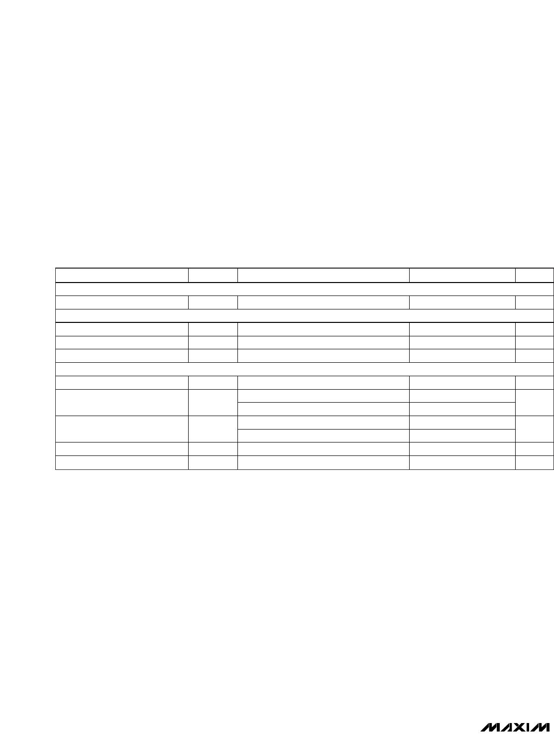
Figure 2 shows the applicable ISO 15693 commands
and their purpose. The network function commands
allow the master to identify all slaves in its range and to
change their state, e.g., to select one for further commu-
nication. The protocol required for these network func-
tion commands is described in the
Network Function
Commands
section. The memory and control functions
access the memory of the MAX66140 for reading and
writing. The protocol for these memory and control func-
tion commands is described in the
Memory and Control
Function Commands
section. All data is read and writ-
ten least significant bit (LSb) first, starting with the least
significant byte (LSB).
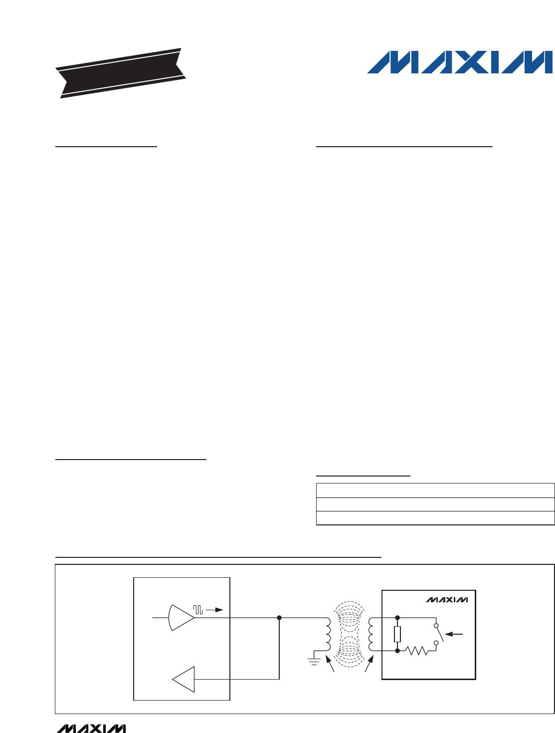
Parasite Power
As a wireless device, the MAX66140 is not connected
to any power source. It gets the energy for operation
from the surrounding RF field, which needs to have a
minimum strength as specified in the
Electrical
Characteristics
table.
Unique Identification Number (UID)
Each MAX66140 contains a factory-programmed and
locked identification number that is 64 bits long
(Figure 3). The lower 36 bits are the serial number of the
chip. The next 8 bits store the device feature code, which
is 03h. Bits 45 to 48 are 0h. The code in bit locations 49 to
56 identifies the chip manufacturer, according to ISO/IEC
7816-6/AM1. This code is 2Bh for Maxim. The code in the
upper 8 bits is E0h. The UID is read accessible through
the Inventory and Get System Information commands.
MAX66140
RF
FRONT-
END
VOLTAGE
REGULATOR
INTERNALSUPPLY
MEMORY AND
FUNCTION
CONTROL
ISO 15693
FRAME
FORMATTING
AND
ERROR
DETECTION
READ/WRITE BUFFER
SECRET
UID
REGISTER
BLOCK
USER
EEPROM
SHA-1
ENGINE
f
c
DATA
MODULATION
Figure 1. Block Diagram
ISO 15693-Compliant Secure Memory
_______________________________________________________________________________________ 3
ABRIDGED DATA SHEET

MAX66140K-000AA+

Mfr. #:
Manufacturer:
Maxim Integrated
Description:
RFID Transponders RFID FOB 15693 ID 1K SECURE LF
Lifecycle:
New from this manufacturer.
Delivery:
DHL FedEx Ups TNT EMS
Payment:
T/T Paypal Visa MoneyGram Western Union

Products related to this Datasheet