MAX66140
ISO 15693-Compliant Secure Memory
12 ______________________________________________________________________________________
ABRIDGED DATA SHEET
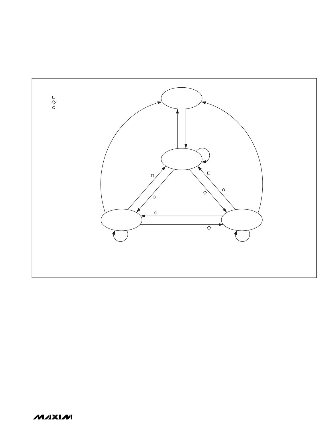
ISO 15693 Slave States and
Address Modes
Initially, the master has no information whether there are
any RF devices in the field of its antenna. The master
learns the UIDs of the slaves in its field from the
responses to the Inventory command, which does not
use the Address_flag and the Select_flag bits. The state
transitions are controlled by network function com-
mands. Figure 16 shows details.
ISO 15693 defines four states in which a slave can be
plus three address modes. The states are power-off,
ready, quiet, and selected. The address modes are
nonaddressed, addressed, and selected. The
addressed mode requires that the master include the
slave’s UID in the request, which increases the size of
the requests by 8 bytes. Table 5 shows which address
mode is applicable depending on the slave’s state and
how to set the Address_flag and the Select_flag bits for
each address mode.
ISO 15693 States and Transitions
Power-Off State
This state applies if the slave is outside the master’s RF
field. A slave transitions to the power-off state when
leaving the power-delivering RF field. When entering
the RF field, the slave automatically transitions to the
ready state.
Ready State
In this state, a slave has enough power to perform any
of its functions. The purpose of the ready state is to
have the slave population ready to process the invento-
ry command as well as other commands sent in the
addressed or nonaddressed mode. A slave can exit the
ready state and transition to the quiet or the selected
state upon receiving the Stay Quiet or Select command
sent in the addressed mode.
Quiet State
In this state, a slave has enough power to perform any
of its functions. The purpose of the quiet state is to
silence slaves that the master does not want to commu-
nicate with. Only commands sent with the addressed
mode are accepted and processed. This way the mas-
ter can use the nonaddressed mode for communication
with remaining slaves in the ready state, which mini-
mizes the size of the request data packets. As long as
no additional slaves arrive in the RF field, it is safe for
the master to continue communicating in the nonad-
dressed mode. A slave can exit the quiet state and
transition to the ready or the selected state upon receiv-
ing the Reset to Ready or Select command sent in the
addressed mode.
Selected State
In this state, a slave has enough power to perform any
of its functions. The purpose of the selected state is to
isolate the slave that the master wants to communicate
with. Commands are accepted and processed regard-
less of the address mode in which they are sent, includ-
ing the Inventory command. With multiple slaves in the
RF field, the master can put one slave in the selected
state and leave all the others in the ready state. This
method requires less communication than using the
quiet state to single out the slave for communication.
For a slave in the selected state, the master can use the
selected mode, which keeps the request data packets
as short as with the nonaddressed mode. A new slave
entering the RF field cannot disturb the communication,
since it stays in the ready state. A slave can exit the
ADDRESS MODES
SLAVE STATES
NONADDRESSED MODE
(Address_flag = 0;
Select_flag = 0)
ADDRESSED MODE
(Address_flag = 1;
Select_flag = 0)
SELECTED MODE
(Address_flag = 0;
Select_flag = 1)
Power-Off (Inactive) (Inactive) (Inactive)
Ready Yes Yes No
Quiet No Yes No
Selected Yes Yes Yes
Table 5. Slave States and Applicable Address Modes
selected state and transition to the ready or the quiet
state upon receiving the Reset to Ready command sent
in any address mode or the Stay Quiet command sent
in the addressed mode. A slave also transitions from
selected to ready upon receiving a Select command if
the UID in the request is different from the slave’s own
UID. In this case the master’s intention is to transition
another slave with the matching UID to the selected
state. If the slave already in the selected state does not
recognize the command, e.g., due to a bit error, two
slaves could be in the selected state. To prevent this
from happening, the master should use the Reset to
Ready or the Stay Quiet command to transition a slave
out of the selected state.
MAX66140
Figure 16. ISO 15693 State Transitions Diagram
POWER-OFF
READY
SELECTEDQUIET
IN FIELD
NOTE 1
NOTE 3
OUT OF FIELD
OUT OF FIELD
RESET TO READY
[N, A, S]
OUT OF FIELD
NOTE 2
RESPONSE LEGEND:
NOTE 1: THE SLAVE PROCESSES THE INVENTORY COMMAND AND OTHER COMMANDS PROVIDED THAT THEY ARE SENT IN THE [N] OR [A] ADDRESS MODE.
NOTE 2: THE SLAVE PROCESSES ONLY COMMANDS SENT IN THE [A] ADDRESS MODE.
NOTE 3: THE SLAVE PROCESSES THE INVENTORY COMMAND AND OTHER COMMANDS IN ANY ADDRESS MODE.
RESPONSE TO
RESET TO READY
RESET TO READY [A]
MATCHING UID
STAY QUIET [A]
MATCHING UID
SELECT [A],
NONMATCHING UID
RESPONSE TO
SELECT
NO RESPONSE
STAY QUIET [A] MATCHING UID
SELECT [A]
MATCHING UID
SELECT [A] MATCHING UID
ADDRESS MODE LEGEND:
[N] NONADDRESSED
[A] ADDRESSED
[S] SELECTED
ISO 15693-Compliant Secure Memory
______________________________________________________________________________________ 13
ABRIDGED DATA SHEET
MAX66140
Request Flags
The command descriptions on the subsequent pages begin with a byte called request flags. The ISO 15693 stan-
dard defines two formats for the request flags byte. The state of the Inventory_flag bit controls the function of the bits
in the upper half of the request flag byte. The function of the request flags is as follows:
Request Flags, Inventory_flag Bit Not Set
Bits 8 and 4: No Function
These bits have no function. They must be transmitted as 0.
Bit 7: Options Flag (Option_flag)
This bit is used with block read commands to include the block security status in the response. If not applicable for a
command, the Option_flag bit must be 0.
Bit 6: Address Flag (Address_flag)
This bit specifies whether all slaves in the master’s field that are in the selected or ready state process the request
(bit = 0) or only the single slave whose UID is specified in the request (bit = 1). If the Address_flag bit is 0, the
request must not include a UID. The combination of both the Select_flag and Address_flag bits being set (= 1) is not
valid.
Bit 5: Select Flag (Select_flag)
This bit specifies whether the request is processed only by the slave in the selected state (bit = 1) or by any slave
according to the setting of the Address_flag bit (bit = 0).
Bit 3: Inventory Flag (Inventory_flag)
This bit must be 1 for the Inventory command only. For all other commands, this bit must be 0.
Bit 2: Data Rate Flag (Data_rate_flag)
This bit specifies whether the response data packet is transmitted using the low data rate (bit = 0) or the high data
rate (bit = 1).
Bit 1: Subcarrier Flag (Subcarrier_flag)
This bit specifies whether the response data packet is transmitted using a single subcarrier (bit = 0) or two subcarri-
ers (bit = 1).
ISO 15693-Compliant Secure Memory
14 ______________________________________________________________________________________
ABRIDGED DATA SHEET
BIT 8 (MS) BIT 7 BIT 6 BIT 5 BIT 4 BIT 3 BIT 2 BIT1 (LS)
0 Option_flag Address_flag Select_flag 0 Inventory_flag (= 0) Data_rate_flag Subcarrier_flag

MAX66140K-000AA+

Mfr. #:
Manufacturer:
Maxim Integrated
Description:
RFID Transponders RFID FOB 15693 ID 1K SECURE LF
Lifecycle:
New from this manufacturer.
Delivery:
DHL FedEx Ups TNT EMS
Payment:
T/T Paypal Visa MoneyGram Western Union

Products related to this Datasheet